초음파 센서의 혼 가이드 형상에 따른 음향 지향성
© The Korean Society for Noise and Vibration Engineering
Abstract
This study addressed horn guides attached to an ultrasonic sensor to improve acoustic directivity. Because an ultrasonic sensor with better directivity can measure longer distances, it is necessary to study methods of improving directivity by attaching a horn guide. We analyzed the acoustic characteristics of an ultrasonic sensor with a horn guide of various shapes by the finite element method in order to observe the acoustic directivity depending on the horn guide shape. We considered conical, exponential, and parabolic horns as well as the hornless case and examined the directional sound pressure distribution at a certain distance from the exciting point of the sensor and sound pressure magnitude along the axial direction. Experiments were performed to verify the analysis results. We used ultrasonic sensors attached with a horn guide to transmit ultrasonic waves and to measure the sound pressure of ultrasonic waves reflected from a plane. The results of finite element analysis and experiments consistently demonstrate the directivity appeared in the order of conical, exponential, and parabolic horns, followed by the hornless case. We observed that the conical horn has the best directivity.
Keywords:
Ultrasonic, Sensor, Directivity, Horn, Shape키워드:
초음파, 센서, 지향성, 혼, 형상1. 서 론
초음파 센서는 장애물 감지 또는 거리측정에 사용되고 있다. 가령, 자동차의 주차보조 및 산업용 수위 계측에 사용되며, 이동로봇이나 드론에서 장애물 탐지에 적용된다(1). 거리측정용 초음파 센서에서 지향성이 좋을수록 측정할 수 있는 거리범위가 길다(2). 따라서 지향성을 향상시키는 방안이 필요하며, 그 일환으로 혼 가이드를 부착함에 있어서 혼 설계가 필요하다.
초음파 센서를 이용한 장애물 인식은 꾸준히 연구되는 주제이다(3). 특히 최근에는 차량에서 주변 장애물을 감지하는 용도로 수요가 많아지고 있다(4). 거리측정용 초음파 시스템에서 가이드를 적용하는 사례가 있는데(5,6), 구체적인 설계 근거가 제시되어 있지 않다.
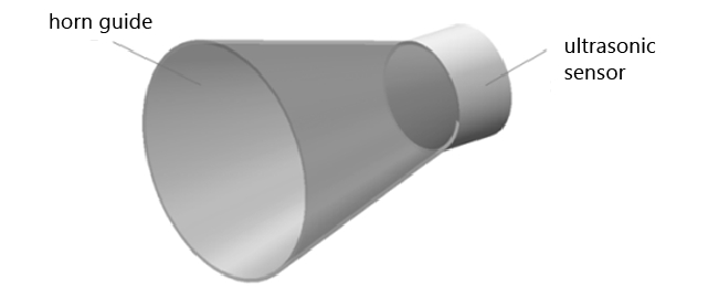
이 연구는 초음파 센서의 음향 지향성 향상을 위해, Fig. 1에 보인 바와 같이 초음파 센서에 부착하는 혼 가이드를 설계하기 위한 과정이다. 우선 혼 가이드 형상을 선정하기 위하여, 여러 형상의 혼 가이드가 부착된 초음파 센서의 음향 지향성을 비교하였다.
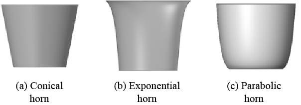
이 연구에서는 Fig. 2에 보인 콘 형상, 지수함수 형상 및 포물선 형상의 혼들과 혼이 없는 경우를 다루었다. 혼 가이드의 목 부분에 배치되는 초음파 센서의 진동에 의해 생성되는 초음파가 혼 가이드를 거쳐 외부로 방사하여 형성하는 음압분포를 유한요소 해석으로 구하였다. 센서 진동부로부터 일정거리 떨어진 지점에서의 방향별 음압 분포로부터 지향성 지수를 산출하여 비교하였다. 또한 센서 진동부 중심 축방향 일정거리에서 음압 크기를 비교하였다. 실험을 하여 해석결과를 검증하였다.
2. 이론적 배경
초음파 지향성을 정량적으로 비교하기 위하여 음향학 이론(8)에서 음향특성 표현 변수들을 선정하였다.
3. 유한요소 해석
여러 형상의 혼에 의한 지향성을 비교하기 위해 유한요소 해석을 하였다. 상용 프로그램인 ANSYS를 사용하였고, 해석을 통해 음압분포를 구한 후 빔패턴, 지향성, 지향성 지수를 산출하였다.
3.1 해석모델
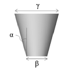
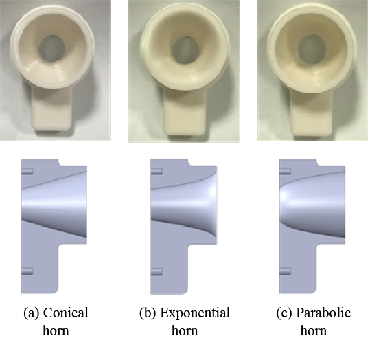
Fig. 2에 보인 세 가지 형상의 혼을 대상으로 모델링하였다. 혼의 치수를 Fig. 3과 같이 나타낼 때 콘 형상 혼의 경우 각도 α를 10°로 설정하여, 혼의 목(throat) 지름 β를 14 mm, 입구(mouth) 지름 γ를 24.6 mm로 하였다. β와 γ를 각각 혼 형상에 상관없이 같게 하였다. 혼의 목 지름은 아이에스테크놀로지㈜에서 제작되는 초음파 센서 지름과 동일하고, 혼의 각도는 MaxSonar社의 MB7076 모델에 따랐다.
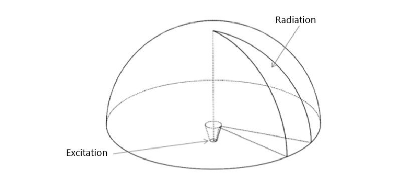
배플(baffle)된 초음파 센서에서 방사하여 전파하는 초음파를 해석하는 영역을 Fig. 4와 같이 반구로 설정하였다. 축대칭 상황이므로 실제 해석에서는 반구를 16등분한 영역을 대상으로 하였다. 혼의 목을 가진주파수 40 kHz인 정현파 신호로 가진하였다. 음속이 343 m/s2일 때 파장 λ는 8.58 mm이므로 요소크기는 λ/8 수준인 1 mm보다 작게 설정하였다. 가진부에 균일분포 가진과 종 모양 불균일분포 가진을 인가하되 가진 크기는 진동가속도 10 m/s2로 하였다.
3.2 해석결과
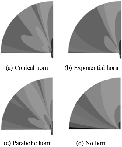
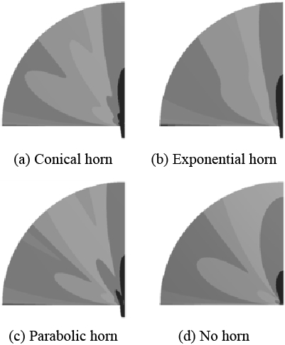
여러 형상의 혼에 대해 균일분포 가진에 의한 음압레벨분포 해석결과를 Fig. 5에 나타내었다. 혼이 없는 경우보다 혼이 있는 경우의 주엽(main lobe)이 크며, 그 중 콘 형상 혼에서 중심축 음압레벨이 가장 크다. 불균일분포 가진에 의한 음압레벨분포 해석결과를 Fig. 6에 나타내었다. 이 결과는 균일분포 가진의 결과와 유사하다.
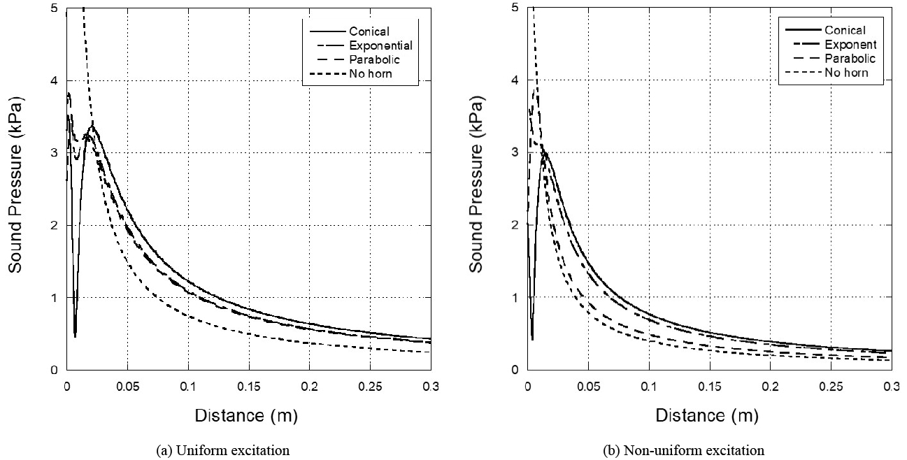
여러 형상 혼에 대해 음압을 Fig. 7에 축방향 거리별 그래프로 나타내었다. 가진부로부터 300 mm 지점에서 음압과 음압레벨을 Tables 1 ~ 2에 기재하였다. 축방향 음압의 크기가 콘 형상, 지수함수 형상, 포물선 형상 혼의 순서로 나타났다.
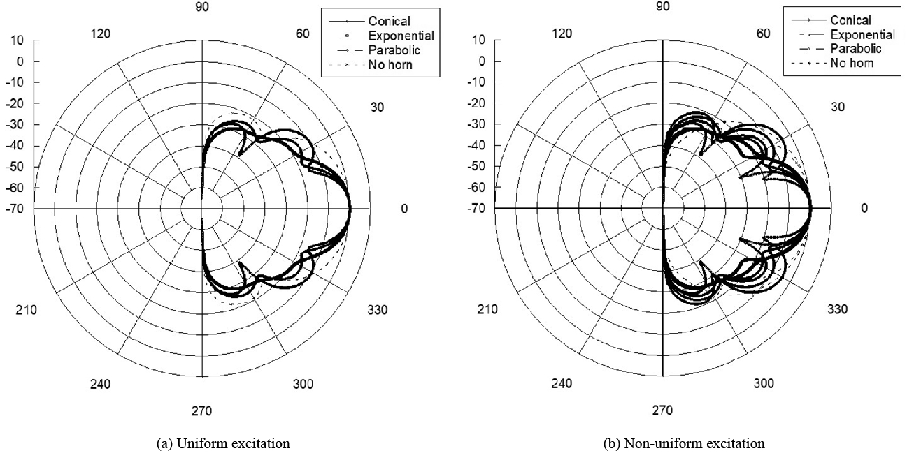
여러 형상 혼에 대해 빔패턴을 Fig. 8에 나타내었다. 이들의 지향성을 Table 3에 기재하였고 지향성 지수를 Table 4에 기재하였다. 음압의 경우와 마찬가지로 지향성 및 지향성 지수가 콘 형상, 지수함수 형상, 포물선 형상 혼의 순서로 나타났다.
4. 실 험
유한요소 해석결과를 검증하기 위해 실험을 하였다. 혼 가이드가 부착된 초음파 센서를 사용하여 초음파를 송신하고, 수신되는 초음파의 음압을 측정하였다.
4.1 실험장치
혼 가이드 시작품을 3D 프린터로 제작하였다. FDM (fused deposition modeling) 방식으로 제작한 혼과 그 단면도를 Fig. 9에 제시하였다. 지름 14 mm인 초음파 센서를 아이에스테크놀로지㈜에서 제작하여 실험에 사용하였다. 이러한 초음파 센서는 차량의 전·후방 감지용으로서 감지거리에 따라 구동주파수가 40 kHz ~ 60 kHz 수준이다. 실험에 사용된 초음파 센서의 고유진동수는 40.7 kHz이다.
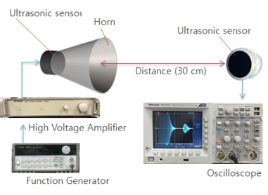
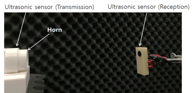
초음파 송수신 계측기 구성도를 Fig. 10에 나타냈다. 실험장치 실제 사진을 Fig. 11에 나타냈다.
신호 발생기(agilent 33120A)를 사용하여 전압크기 10 Vp-p인 40 kHz 정현파를 생성하고, 고전압 증폭기(eliezer HA400)로 증폭해서 초음파 센서를 가진하여 초음파를 송신하였다. 일정거리 전파한 초음파를 센서로 수신하여 오실로스코프(tektronix TDS 3012C)로 관찰하였다.
4.2 실험결과
초음파 전파 거리는 300 mm로 하였다. 지면으로부터 500 mm 높이에서 실험하여 지면의 영향을 예방하였다. 여러 형상의 혼 가이드에서 송신된 초음파를 수신하여 출력크기를 측정하였다. 혼 가이드 형상에 따른 출력크기 비교를 위해 혼이 없는 경우를 기준으로 수신된 전압을 정규화하였다. 유한요소 해석결과와 함께 실험결과를 Table 5에 기재하였다. 실험결과 음압이 콘 형상, 지수함수 형상, 포물선 형상 혼의 순서이고 유한요소 해석에서 나타난 경향과 같다.
5. 결 론
이 논문은 혼 가이드 형상에 따른 초음파 센서의 지향성을 다루었다. 콘 형상 혼, 지수함수 형상 혼, 포물선 형상 혼을 선정하였다. 여러 형상의 혼에 대해 지향성을 유한요소 해석을 통해 비교하였다. 반구를 16등분한 영역을 해석모델로 삼았다.
해석결과를 검증하기 위해 음압 측정 실험을 하였다. 이를 위해 3D프린터로 혼 가이드 시제품을 제작하였고, 혼이 부착된 초음파 센서를 사용하여 초음파를 송신하고 일정거리에서 수신된 초음파의 음압을 측정하였다. 여러 형상의 혼에 대해 축방향 음압을 비교하였다.
유한요소 해석과 실험을 통해 초음파 센서에서 혼에 따른 지향성 크기가 콘 형상, 지수함수 형상, 포물선 형상 혼의 순서임을 확인하였다.
Acknowledgments
A part of this paper was presented at the KSNVE 2018 Annual Spring Conference
이 연구는 2017년도 산학연협력기술개발사업(C0531965)의 지원에 의해 수행되었음.
References
- Kim, J. O., (2000), Sensors and Actuators Using Ultrasound, Journal of the Korean Society for Noise and Vibration Engineering, 10(5), p723-728.
-
Seon, S. O., Kim, J. O., Chae, M. K., and Yoo, G. S., (2018), Acoustic Characteristics Depending on the Vibration Distribution of Ultrasonic Sensors, Transactions of the Korean Society for Noise and Vibration Engineering, 28(4), p490-500.
[https://doi.org/10.5050/KSNVE.2018.28.4.490]

- Yu, B., Kwon, S., and Kim, J., (2017), Development of Obstacle Recognition System Using Ultrasonic Sensor, Journal of the Korea Industrial Information Systems Research, 22(5), p25-30.
- Jo, Y. S., (2013), Device for Detecting the Obstacles around the Vehicle and method thereof, Korea Patent Application 10-2013-0075794.
- Lee, J. L., (1997), Ultrasonic Waves and Its Usage, Sehwa, p114.
- Ju, X., Gu, L., and Dong, X., (2014), Application and Research of Ultrasonic Horn in Ultrasonic Ranging System, Sensors & Transducers, 170(5), p60-66.
- Kinsler, L. E., (1999), Fundamentals of Acoustics, 4th edition, Wiley, New York, p171-193.

Sung Gu Lim received the B.S. degree in mechanical engineering from Soongsil University in 2014. Since 2017 as a graduate student at Soongsil, he has been working on ultrasonic sensors and wave propagation.
Jin Oh Kim received the B.S. and M.S. degrees in mechanical engineering from Seoul National University in 1981 and 1983, respectively, and the Ph.D. degree from University of Pennsylvania in 1989. For ten years he has got research experiences at Korea Research Institute of Standards and Science, Northwestern University, and Samsung Advanced Institute of Technology. Since 1997, he has been working at Soongsil University, where he is currently a Professor of mechanical engineering. His research interests are in the area of ultrasonic sensors and actuators using mechanical vibrations and waves.
