Development of Structural Displacement Finite Element Codes Based on Physical Coordinates and High Performance Computing Methods Including PARDISO, PCG, GMRES and MATLAB or OCTAVE Intrinsic Operator ‘\’
‡ Recommended by Editor Won Ju Jeon
© The Korean Society for Noise and Vibration Engineering
Abstract
This paper presents physical coordinate-based 3-node triangular, 4-node rectangular, and 4-node quadrilateral FE codes on the Kirchhoff thin plate theory. Isoparametric 4-node quadrilateral and 4-node plate shell FE codes based on natural coordinates are also presented. The calculation time needed to solve a system equation was compared using direct, iterative, and full matrix and sparse matrix solvers including Gauss elimination method, CG, DGESV, DSGESV, SOR, PCG, GMRES, FGMRES, MGMRES, PARDISO, etc. The full matrix and the sparse matrix were applied to compare the computing time of the system equation using OCTAVE or the MATLAB intrinsic operator ‘\’. The computation times for PCG methods using four types of preconditioners were also compared. The computation time of the finite element method is compared with that of the PCG method after processing the system matrix with the full matrix and sparse matrix forms. We showed that PARDISO and sparse MATLAB or OCTAVE operator ‘\’ could be useful and effective methods for conducting large-scale finite element analyses using personal computers.
초록
이 논문에서는 키르히호프 평판 이론에 기초하여 물리적 좌표기반 3절점 삼각형 유한요소, 4절점 직사각형 유한요소, 4절점 사각형 유한요소 코드들을 제시하였다. Natural coordinates에 기반한 isoparametric 4절점 사각형 유한요소 코드와 4절점 plate shell 유한요소 코드도 제시하였다. 직접법, 반복법 및 full matrix 해법들과 희박행렬 해법들을 이용하여 시스템 방정식을 푸는데 필요한 계산시간을 비교하였다. Gauss 소거법, CG, DGESV, DSGESV, SOR, PCG, GMRES, FGMRES, MGMRES, PARDISO 법 등을 비교 검토하였다. OCTAVE와 MATLAB에 내장된 연산자 ‘\’를 full matrix 형태와 희박행렬 형태 시스템 방정식에 적용하여 계산시간을 비교하였다. 4가지 종류의 preconditioners를 채택한 PCG 방법들에 대한 계산시간도 비교 검토하였다. 또한, 유한요소법에서 시스템 행렬을 full matrix와 희박행렬로 처리한 후에 각각의 경우에 PCG 방법을 적용했을 때의 계산시간도 비교하였다. PC에서도 PARDISO와 sparse MATLAB 연산자 ‘\’를 사용하여 대규모의 유한요소 해석을 수행할 수 있음을 보였다.
Keywords:
Analytical Integration, CG, Conjugate Gradient, Direct Solver, GMRES, Generalized Minimal RESidual, FGMRES, Flexible Generalized Minimal RESidual, Iterative Solver , Kirchhoff-Love Plate, Krylov Subspace Method, MATLAB or OCTAVE Intrinsic Operator ‘\’, MGMRES, Multiple (Restarted) Generalized Minimal RESidual, Mindlin-Reissner Plate, PARDISO, PARallel DIrect Sparse sOlver, PCG, Preconditioned Conjugate Gradient, Physical Coordinates Based FEM, Sparse Matrix Solver키워드:
해석적 적분, 켤레 기울기법, 직접 해법, 일반화된 최소 잔차법, 유연한 일반화된 최소 잔차법, 반복 해법, 키르히호프-러브 평판, 크릴로프 부 공간 법, 매트랩 또는 옥타브 내재 연산자 ‘\’, 다중 일반화된 최소잔차법, 민들린-라이즈너 평판, 병렬 직접 희박 해법, 선조건 적용 켤레 기울기법, 물리적 좌표기반 유한요소법, 희박행렬 해법1. History and Research Motivation of Thin Plate Analysis
In this paper, the development of structural displacement finite element method (FEM) codes and the computational time comparisons of system equation using several solvers were described. For the first topic, we dealt with the Kirchhoff flat plate theory in Section 2, and described the formulations of the finite element (FE) in Section 3. We verified the validity of the developed FE codes in Section 4. As a second theme, in Section 5, we compared the computation times obtained by various solving methods of the system equation within structural static displacement FE codes, and proposed an appropriate analysis methods. Acoustic BEM (boundary element method) code and structural vibration FEM code were needed to perform structural-acoustical coupling analysis by developing high-speed computations of large degrees of freedom without using commercial software. The reason for developing the structural displacement analysis FEM program was that Holmström(1) omitted the FEM program for vibration analysis with blackbox in the program presented in the vibration-acoustic coupled analysis paper. (1) In this paper, the first developed FEM codes were the same as rectangular FE codes presented by Irvine(2 ~ 4). It was a physical coordinate based rectangular FE codes that could be applied only when the four sides were all parallel to the x or y axis(2), developed according to the assumptions used in the Kirchhoff plate theory (thin plate theory). (2) Semie suggested a physical coordinate based 3-node triangular plate FE codes that could model arbitrary two-dimensional shapes and analyzed the displacement of a thin plate(5). He investigated two cases where four sides of the square plate were simply supported or fixed (clamped). However, the analytical results were significantly deviated from the values of the commercial software ANSYS® and Kirchhoff thin plate’s theory. In this paper, we developed a physical coordinate based triangular FE codes according to the methodology suggested by Semie, and found that there would be some errors in the FE codes presented by Semie. (3) We have also developed a physical coordinate based 4-node quadrilateral FE codes that can model any two-dimensional shape in order to complement the disadvantages of FEM using rectangular FEs parallel to the x- or y-axis. (4) On the other hand, the above three FE codes were assumed to ignore transverse shear strain effects because of the Kirchhoff thin plate theory. Ferreira proposed an isoparametric quadrilateral FE codes based on the Mindlin-Reissner plate theory, which considered transverse shear deformation(6). We also developed the natural coordinates based isoparametric quadrilateral FE codes which were based on the thick plate theory, and compared with the displacement analysis results of the Kirchhoff plate theory. (5) The displacement analysis FEM codes based on the Kirchhoff plate and Mindlin-Reissner plate theories were able to only analyze the z-direction displacement in the normal direction of the 2-D coplanar plate. Kwon proposed a 3-dimensional isoparametric plate shell FE codes for static displacement analysis in 3-D space using MATLAB® language(7). We have translated this codes into FORTRAN ones to improve memory scalability and computational speed. Consequently, four 2-D coplanar structural FE codes and one 3-D structural displacement FE codes were described in this paper. The differences between Kirchhoff theory, Mindlin-Reissner plate theory and three dimensional plate shell element were described for two dimensional plate. In order to evaluate the performance of FEM system equation, which was a system matrix equation Ax=b, the computation times of MATLAB®, OCTAVE® and FORTRAN codes were compared in both direct and iterative methods. We also compared the computation time for full matrix solvers that processed the coefficient matrix A of system equation as a full matrix form and sparse matrix solvers for the sparse matrix one. The computation times for PCG methods using four kinds of preconditioners were also compared in sparse system matrix. The finite element method was compared with the computation time of PCG method after processing the system matrix with full matrix and sparse matrix form, respectively.
2. Kirchhoff Thin Plate Theory
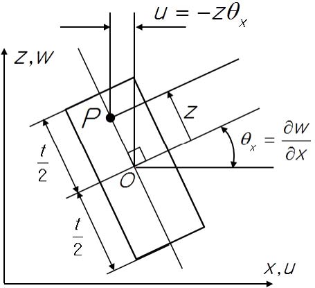
According to Semie(5), in 1776 Euler first attempted to solve the free vibration problem of the plate. Germain developed differential equations for flat plates without considering warping term, and Lagrange proposed general plate differential equations by considering warping term. Poisson proposed the Germain-Lagrange plate equation assuming a constant flexural rigidity for the plate subjected to static loads. Navier has established a flat bending theory that uses flexural rigidity as a function of plate thickness and proposed a method to obtain exact solution using Fourier trigonometric series. Kirchhoff proposed the theory of plate bending using basic assumptions known as ‘Kirchhoff's hypothesis.’ Kirchhoff's thin plate’s hypothesis is expressed: the cross sections of the plate are remained as straight and unstretched and also normal to midsurface even after the plate is deformed. That is, γxz=0, γyz=0, σzz=0 and εzz=0. Let the reference in the z direction be the middle of the plate thickness, and the displacements in the x and y directions in the plate u, v respectively, and the displacement in the z direction w (Fig. 1).
| (1) |
| (2) |
For inplane strains, strain-displacement relationships:
| (3) |
| (4) |
| (5) |
The relationship between plane stress and plane strain for isotropic materials according to Kirchhoff’s assumptions is as follows. Stress-strain relationships:
| (6) |
| (7) |
| (8) |
Where, shear modulus , Young’s modulus E, Poisson’s ratio υ
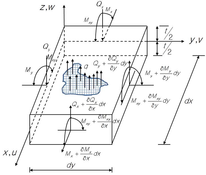
Bending moments(7) along the x, y, and xy edge (Fig. 2):
| (9) |
| (10) |
| (11) |
Where, bending rigidity of the plate and t is thickness of the plate.
By the moment equilibrium,
| (12) |
| (13) |
| (14) |
Inserting Eq. (9) ~ Eq. (11) into Eq. (13) and Eq. (14), after
| (15) |
This is the governing equation for Kirchhoff thin plate bending theory with transversely loaded.
2.1 Analytical Solution of Thin Plate
Boundary conditions for a simple supported rectangular plate: width and length of the plate are a and b, respectively.
Using the infinite double Fourier trigonometric series satisfying the boundary condition in the method proposed by Navier(5,8), out of plate displacement w(x, y) can be expressed as Eq. (16).
| (16) |
| (17) |
| (18) |
Eq. (16) and Eq. (17) can be inserted into Eq. (15) and solved w(x, y), but Levy(8) proposed a simple series method and got the maximum displacement at the center of the square plate (a=b).
| (19) |
The displacement due to concentrated load P at the center of the square plate is followed(8).
| (20) |
The maximum displacements at the center of the square plate with respect to the distributed loads p0 and concentrated loads P for the fixed boundary conditions are given by Eq. (21) and Eq. (22)(8).
| (21) |
| (22) |
3. Formulations of Various Structural Displacement Finite Elements
In this paper, three-node triangular, four-node rectangular and quadrilateral FE codes based on physical coordinates and Kirchhoff thin plate theory were presented and also natural coordinates based isoparametric four-node quadrilateral FE codes according to Reissner-Mindlin thick plate theory and 3-D plate shell FE codes. According to Kirchhoff’s thin plate theory, the transverse shear strain energy is negligible compared to the bending energy. Therefore, the total strain energy of the plate(2) is as Eq. (23).
| (23) |
| (24) |
| (25) |
Total potential energy Π, potential energy of external forces V
| (26) |
Where,
3.1 Triangular Finite Element Based on Physical Coordinates
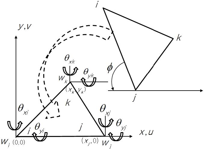
Batoz proposed a DKT (discrete Kirchhoff theory) element(9) with the origin of the local coordinate of the geometric centroid of the triangle. But, in this paper, the origin of the local coordinates was defined as in Fig. 3. In Fig. 3, let the longest side of the triangular element coincide with the x-axis of the local coordinates. The local triangle with new coordinate values was constructed by translational and rotational movement so that the vertex facing the longest side was in the first quadrant. FE codes using 9 degrees of freedom (DOF) triangular element with 3 DOF per the triangular node were developed. The node numbering order was counterclockwise. Local FEs constructed from local coordinates were converted to their original global coordinates by rotational movement. The global total stiffness matrix was constructed by assembling each global FEs. W was out of plane displacement in z coordinate and was expressed by physical coordinates like as Eq. (27)(5).
| (27) |
| (28) |
| (29) |
For node i,
After applying the same processes for node j and node k,
| (30) |
| (31) |
That is,
| (32) |
| (33) |
Where, [C]=[B]-1
Equation (23) can be rewritten as Eq. (34).
| (34) |
Local element stiffness matrix [k]e,
| (35) |
| (36) |
Where, β=2(1-υ)
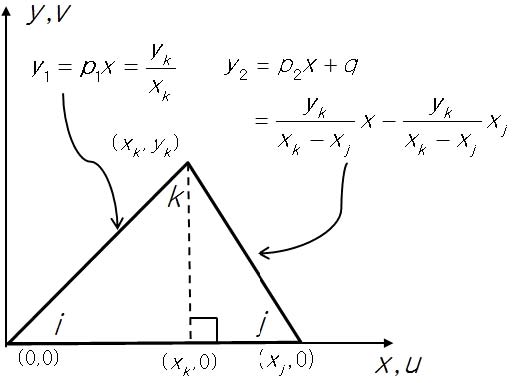
Analytical area integration (Fig. 4) for S47 = 12x,
Where, p1=yk/xk, p2=yk/(xk-xj), q=-xjp2
Global element stiffness matrix [k]g was obtained like as follows.
| (37) |
Where, rotation matrix
By variational approaches for Eq. (26),
| (38) |
Total global stiffness matrix, displacement vector and force vector were followed, respectively.
| (39) |
| (40) |
| (41) |
System equation was expressed as Eq. (42).
| (42) |
3.2 Rectangular Finite Element Based on Physical Coordinates
According to Tom Irvine(2), the out of displacement W can be expressed as physical coordinates as 4 DOF at each of four vertices of a rectangle.
| (43) |
The FE could be obtained in the same way as Sec 3.1. For S47 = 12x,
Where, a and b was side length of rectangular element.
Analytical area integration was simple compared to triangular FE, but rectangular FE suggested by Irvine could be applied only if all sides were parallel to x or y axis. However, in this paper, even though the local rectangular element was not parallel to the x or y axis, we have modified the FE codes so that it could be applicable to any orientation of rectangle FE by applying the rotational transformation as shown in Eq. (37).
3.3 Quadrilateral Finite Element Based on Physical Coordinates
Batoz developed the DKQ (discrete Kirchhoff quadrilateral) element by extending the DKT concept. However, the results of the convergence rates during displacement analysis were not good compared to McNeal or LORA by Robinson and Haggenmacher(10). In this paper, quadrilateral FE were developed by the same physical coordinate based methodology as the triangular FE mentioned in Sec 3.1. The FE formulation process was the same as the triangular FE in Sec 3.1, but the analytical area integration was very lengthy and was obtained using software.
3.4 Isoparametric Quadrilateral Finite Element (Mindlin-Reissner Thick Plate Theory) Based on Natural Coordinates
Mindlin-Reissner, Naghdi plate theory(6,7,11 ~ 13) used a generalization of the Kirchhoff hypothesis: points of the plate which are on the normal to the undeformed middle surface remain on a straight line even after deformations are proceeded but, which are not necessarily normal to the deformed middle surface(11). That means γxz≠0, γxz≠0, σzz=0 and εzz=0. Therefore, shear deformation term was added to traditional Kirchhoff plate theory, Eq. (23) as a second term.
| (44) |
| (45) |
| (46) |
Where, α is shear correction factor(6), 5/6, {σc} and {εc} are stress and strain due to shear deformations. Transverse shear strain-displacement relationship(6):
| (47) |
| (48) |
| (49) |
| (50) |
Where,
With the shape function,
| (51) |
| (52) |
| (53) |
| (54) |
| (55) |
| (56) |
| (57) |
| (58) |
| (59) |
| (60) |
3.5 Plate Shell Finite Element Based on Natural Coordinates
Kwon proposed MATLAB® FE codes using plate shell finite element, 5 DOFs per node, which combined membrane element and plate bending element using natural coordinates based isoparametric elements(7). Since the inplane rotational term was not included in plate shell element, it left null or zero values in the stiffness matrix. So-called drilling DOF incurred singularity in structural stiffness matrix if all the elements were coplanar(7). To solve this problem, Knight(14) suggested that a very small value be specified for the stiffness of the drilling DOF so that the contribution to the strain energy equation from this term would be zero(7). The local stiffness matrix in the natural local coordinates was transformed into the global coordinates and assembled to obtain the total global stiffness matrix.
4. Validation
The FE codes suggested in Section 3 were validated using a square plate with four sides fixed. The plate specifications and the analysis conditions used in the analysis were as followed. Young’s modulus E=2×10¹¹Pa, Poisson ratio υ=0.285, density ρ= 7874kg/m3 and width×length, 1m×1m with thickness 0.1m. A square plate with a uniform distribution load of 50000Pa was modeled on a 10×10, 20×20, 40×40 grids on a flat plate. Theoretical calculations, results calculated from the Semie model(5), ANSYS® shell 63, ANSYS® shell 163 and LISA® software are shown in Table 1. The results using the five FE codes suggested in Section 3 are also presented. The displacement at the center of the square plate calculated by the theoretical formula (Eq. (21)) was ‒3.47μm. Semie model using triangular FE showed a displacement of ‒4.81μm when modeling a square plate at 100×100. It was 38.6% error compared with the value predicted by the theoretical Eq. (21), and it was also reported that the error was ‒42.4% and 384.15%, respectively, when using ANSYS® shell 63 and ANSYS® shell 163 element (5). However, in Sec 3.1, the result using the triangle FE codes formulated by the methodology proposed by Semie was ‒3.50 μm, which was within 0.9% of the theoretical value. The FE codes presented in Sec 3.1 ~ Sec 3.3 which were formulated according to the Kirchhoff thin plate theory showed a maximum error of 0.9% with the theoretically predicted value. Therefore, there would be some errors in the FE codes programmed by Semie, and it was assured that the analys using ANSYS® software was also applied incorrectly. Consequently, it showed that the FEM codes formulated according to the Kirchhoff thin plate theory were suitable for use. The analysis result by the commercial software LISA® version 8.1.0 beta version was 16.14%. In case of Mindlin-Reissner thick plate theory considering shear deformation, it showed 8.6% error with Kirchhoff thin plate theory. On the other hand, 3 dimensional plate shell FE codes showed 19.02% error with Kirchhoff thin plate theory.
5. Comparison of Computation Time for System Matrix According to Solving Methods
It can be classified by two regimes to obtain the solution of the system equation, Ax=b. One is full matrix solving methods with A(i, j) form of square coefficient matrix A and the other sparse matrix solving methods with coefficient matrix A as sparse form.
5.1 Full Matrix Solving Methods
The FE codes developed in Section 3 initially were coded in OCTAVE® language because of necessity of graphic postprocessing in the coding stage. OCTAVE® intrinsic operator ‘\’ was adopted to obtain the vector x in the system equation Ax=b. But, it needed a long computation time, and codes were translated to FORTRAN language in order to improve its computing performance. In order to find the solution vector in the system equation Ax=b, which was the form [K]{W}={F} used in the structural displacement FE codes in Section 3, and compare computing performance, the following eight full matrix solving methods including four methods described in reference(15) were examined.
- (1) Gauss elimination method with partial pivoting algorithm, direct solving method.
- (2) Successive over-relaxation (SOR(ω=1.95)) algorithm, iterative solving method.
- (3) Conjugate gradient (CG) Algorithm, iterative solving methods, tolerance=10-11.
- (4) Preconditioned conjugate gradient algorithm with diagonal preconditioner (PCG-D), iterative solving method, tolerance=10-11.
- (5) Direct Gauss elimination method with partial pivoting (DGESV), FORTRAN MKL® library.
- (6) Iterative Gauss elimination method with partial pivoting (DSGESV), FORTRAN MKL® library.
- (7) OCTAVE® ‘\’, full matrix solver (OCT-F).
- (8) MATLAB® ‘\’, full matrix solver (MAT-F).
Methods(1) to (4) showed that the same algorithmic codes were simply translated in OCTAVE®, MATLAB®, and FORTRAN languages, respectively, rather than using specialized built-in functions in each language. There were two classes of iteration methods(16). One was stationary iteration methods or fixed-point iteration methods like as Jacobi, Gauss-Seidel, SOR and the other was projection methods, which was called Krylov subspace method, like as CG, PCG, generalized minimum residual method(GMRES). Projection methods were required that approximation solution x extracted from the subspace K should make residual x=b‒Ax orthogonal to the subspace L. In the first stage, the system coefficient matrix A used in the simulation was a symmetric positive definite (SPD) matrix, a tridiagonal matrix with a bandwidth of 1+2 × nx, with one diagonal with four off-diagonal terms added(17). Nx was the distance between diagonal term and element locations and n was the size of matrix A.
The vector b is obtained by assuming x(1:n) = 1 in Ax=b. The personal computer (PC) used was Intel® Core i7 4790K@4.0GHz processor, 32GB RAM, and operating on Windows 7 64bit. FORTRAN codes were compiled using Intel® Parallel Studio XE 2015 MKL compiler 64bit. In the case of 2000DOF, the calculation time ratio was 27 883 sec: 144.24 sec:32.26 sec = 864 : 4 : 1 when the Gauss elimination method(solid line) was excuted with OCTAVE®, MATLAB®, and FORTRAN language, respectively (Fig. 5). In the case of the PCG-D algorithm, it showed OCTAVE® : MATLAB®:FORTRAN=21436sec:70.31sec:1.12 sec=19139:63:1. When the Gauss method and the SOR method were used, the calculation time ratio of OCTAVE®/MATLAB® was 193 and 197, CG method and PCG-D was 355 and 305, respectively. That is, it showed that the computing speed was 193 to 355 times faster to operate in MATLAB® than in OCTAVE® for same algorithmic codes. In addition, executing similar codes in FORTRAN was 4 to 63 times faster than running in MATLAB®, and 831 to 2269 times faster than in OCTAVE® between 200 DOF and 10000 DOF. The PCG-D method in FORTRAN showed the fastest calculation time.
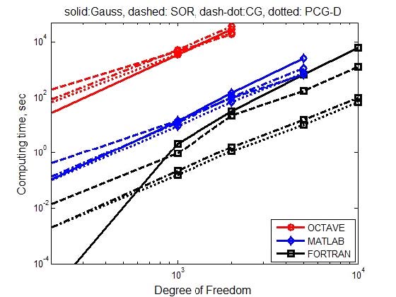
Comparison of computing time using full matrix solvers for OCTAVE®, MATLAB® and FORTRAN codes for 5 model cases, marker: O: OCTAVE®, ◇: MATLAB®, □: FORTRAN, linestyle: -: Gauss, --: SOR, -.: CG, ▫▫: PCG-D, range: 200 DOF ~ 10 000 DOF (Unit: sec)
Fig. 6 showed the computing time when the operator ‘\’ built in OCTAVE® and MATLAB®, the FORTRAN MKL library direct solver DGESV and iterative solver DSGESV were used. The shortest computation time for 2000 DOF was 0.051 sec for the direct method DGESV and 21436sec (≒10hours) for the slowest case, OCTAVE®-PCG-D (marker: blue ●). It showed OCTAVE®-PCG-D:MATLAB®-PCG-D: FORTRAN-PCG-D:OCTAVE ‘\’:MATLAB ‘\’:DGESV =21436:70.31:1.12:0.637:0.065:0.051=420314: 1379:22:12.5:1.27:1. In the case of MKL FORTRAN library, iteration method was faster than direct method at 5000 DOF or more. In view of above discussions, it showed that the program language and solving method to be used were very important in computing time of system equation. The intrinsic operator ‘\’ used in MATLAB® was shown to be an effective method. Using the MATLAB® ‘\’ (-◆-) showed 1080 times faster than the computing time of the PCG-D programmed in MATLAB® language(◆) in case of 2000DOF. For 10000DOF system equation, FORTRAN-PCG-D was 69.3sec (Fig. 5), DGESV 4.5sec, OCTAVE® ‘\’ 104.4sec, and MATLAB® ‘\’ 3.3sec(Fig. 6), respectively.
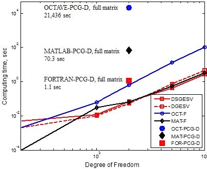
Comparison of computing time using full matrix solvers, marker-line: ●: OCTAVE®-PCG-D, O-: OCTAVE® ‘\’, ◆: MATLAB®-PCG-D, ◇-: MATLAB® ‘\’, ■: FORTRAN-PCG-D, □-: DSGESV, □--: DGESV, range: 200 DOF ~ 10 000 DOF (Unit: sec)
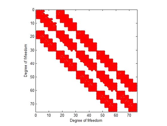
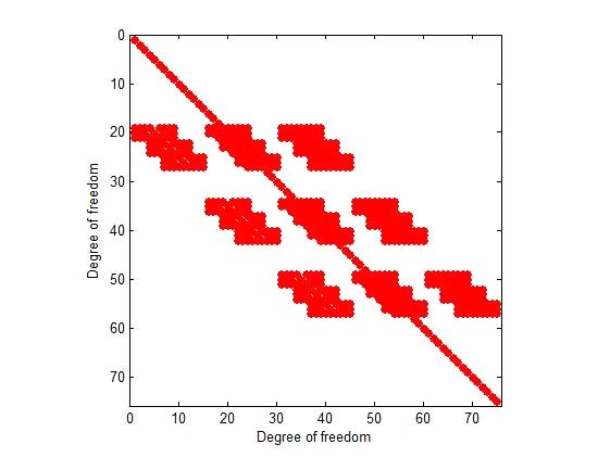
So far we have compared the computation times for the cases where the coefficient matrix A was ideally diagonally banded SPD matrix. Gauss and SOR method, which was stationary iteration method with slow computation speed, were excluded from comparison. Using the data obtained from the FEM codes in Section 3.2, the computational speeds for the system equations were compared. In the formal FEM, the stiffness matrix [K] typically exhibited the characteristics of SPD matrix(18). The stiffness matrix and the force vector were obtained using FEM codes using the rectangular FE codes in Sec. 3.2. The square plate were modeled to 20×20, 40×40, 80×80, 100×100, 140×140 FE meshes, respectively, which was called Ex1, Ex2, Ex3, Ex4 and Ex5. Since the DOF per node was 3, each model size was 1323, 5043, 19683, 30603, 59643 DOF, respectively. The specifications, boundary conditions and force conditions of the square plate were described in Section 4. The stiffness matrices and force vectors were obtained by applying fixed boundary conditions to the four sides of the square plate. The stiffness matrices and force vectors for the five data sizes were output to data files and then used in each solving method programs. Fig. 7 and Fig. 8 showed the stiffness matrices before and after applying the boundary condition to the system equation of the case of square plate (4×4) (75DOF). The modified stiffness matrix pattern (Fig. 8) was a general matrix form and obtained by applying fixed boundary conditions to the stiffness matrix pattern in Fig. 7.
Table 2 showed the calculation times obtained using the following seven solving methods for the five matrix size models. Methods(1) ~ (4) were compiled with Intel® Parallel Studio XE 2015 FORTRAN compiler. Fig. 9 showed the computation time results for each solver.
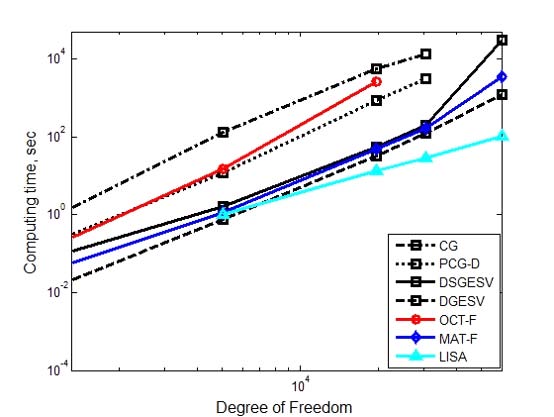
Comparison of computing time using full matrix solvers for 7 methods, marker-line: □-: DSGESV, □--: DGESV, □-.: CG, □▫▫: PCG-D, O-: OCTAVE® ‘\’, ◆- : MATLAB® ‘\’, ▲-: LISA®, range: 1323 DOF ~ 59 643 DOF (Unit: sec)
- (1) CG codes(15), iterative method.
- (2) PCG-D codes(15), diagonal preconditioner, iterative method.
- (3) DSGESV, iterative Gauss elimination method with partial pivoting.
- (4) DGESV, direct Gauss elimination method with partial pivoting.
- (5) OCTAVE® operator ‘\’, OCT-F.
- (6) MATLAB® operator ‘\’, MAT-F.
- (7) LISA® software, version 8.1.0 Beta version.
In the direct solution method DGESV (□ dashed line), it showed that the calculation time was nearly proportional to DOF3. In MATLAB® operator ‘\’, it was 0.065sec at 1323DOF and 3443sec at 59643 DOF, the computation time was also proportional to DOF3. In Fig. 6, iterative method DSGESV showed faster calculation speed than direct method DGESV, but in Fig. 9, iterative method showed slower calculation speed. This was because the coefficient matrix A applied in Fig. 6 was a sparse SPD matrix and the matrix A used in Fig. 9 was a non-SPD matrix and a relatively dense matrix. In OCTAVE® and MATLAB®, the same operator ‘\’ was used. As the DOF increases, the calculation time difference between MATLAB® and OCTAVE® becomes larger. When calculating the FE model of 19683DOF (Ex3), the computation time ratio was 55 times as 47 seconds in MATLAB® and 2581 seconds in OCTAVE®. In the case of 59643 DOF (Ex5), it was 3443sec for MATLAB® ‘\’ and 1218 sec for DGESV routine. There was a rapid increment in computing time at 59643DOF for DSGESV. The reason why the computing time using DSGESV, an iterative method, surged compared with the direct method DGESV, was that it was caused by a reduction in efficiency caused by using virtual memory due to lack of CPU memory. Unlike DGESV, DSGESV, an iterative method, required additional workspace memory equal in size to system matrix A. To calculate an Ex5 model using DSGESV, we needed at least 56GB of memory, but used PC had hardware specifications with 32GB of RAM, so it needed virtual memory and so, it utilized hard disk as a virtual memory source, which resulted in a slower overall memory accessing time than using only CPU memory in direct solver DGESV. That is, by using hard disk memory rather than CPU memory as swap memory, the DOF was increased 1.9times in Ex5 compared to Ex4, but the calculation time was 31236sec which was 155 times larger than 202sec in Ex4. Therefore, in the case of Ex5, 59643DOF, DSGESV was needed 8hours 41minutes (31236sec), MATLAB® solver ‘\’ 57minutes (3443sec) and DGESV took 20min (1218sec). In all cases, the direct solver, the DGESV routine showed the fastest calculation speed. For the commercial software LISA®, the solving time was 106sec. A comparative analysis of Table 2, Fig. 5 and Fig. 6 revealed interesting facts. It was summarized the calculation time for 5000 DOF in Table 3.

Comparison of computing time using full matrix solvers for general matrix (Ex2) and sparse SPD matrix(Unit: sec)
Direct solver DGESV showed almost the same calculation time in both cases. The iterative solvers, CG and DSGESV, showed 4-8 times faster computing time with the SPD coefficient matrix in system equation. This was because the DOF was almost the same, but the SPD matrix was a sparser matrix than Ex2. Even when the MATLAB® operator ‘\’ was used, the calculation time was half shorter in the sparse matrix SPD. As an interesting result, the direct method DGESV in Ex2 showed faster calculation speed than the iterative method DSGESV, but the iterative method showed faster calculation time than the direct method in sparse matrix SPD. That is, when the number of non-zero coefficients was small, the iteration method showed faster calculation speed than the direct method.
5.2 Sparse Matrix Solving Method
In Section 5.1, full-matrix solving methods were used to examine the computing times in system equation for the SPD coefficient matrix (Figs. 5 ~ 6, 200 DOF ~ 10000 DOF) and for the stiffness matrix obtained in the structural displacement FEM (Table 2, 1323 ~ 59643 DOF). Practically, there were limitations on the size of matrix that could be solved due to full matrix memory space. Also, since the matrix operation was performed on the ‘0’ values in the coefficient matrix A (Figs. 7 ~ 8), lots of calculation time was required for full matrix solvers. If there were many ‘0’ values in coefficient matrix A, using a sparse solver would be benefit from memory savings and computation speed. In order to use the sparse matrix solving methods, the system matrix A must be converted from full matrix form to a sparse matrix one. In OCTAVE® and MATLAB®, the sparse matrix solver used the ‘\’ operator, which was the same form as the full matrix solver. However, the system matrix A must be transformed into a sparse matrix form. In this paper, it was adopted in order to make the system coefficient matrix A a sparse matrix form, one-based indexing CSR (compressed sparse row) format(19 ~ 21) in FORTRAN codes and CSC (compressed sparse column) format in MATLAB® and OCTAVE® codes, respectively. NNZ (number of non-zero) was defined the number of non-zero coefficients in the coefficient matrix A whose size was n×n is. Sparsity (%) is defined as sparsity (%)=NNZ/(n×n)×100. Table 4 and Table 5 showed the DOF, NNZ, and sparsity(%) of the data to be used in this section and the amount of memory required to store matrix A in full matrix and sparse matrix. Table 4 showed that the 50000 DOF (#7) model required 20GB of memory to process a full matrix of coefficients A, but a sparse matrix required only 2MB, which was 0.01% of the original memory requirement. 300000DOF (#10) required 720GB of memory for the full matrix, but it could not be handled by general PCs. However, if sparse matrix form is used, only 12MB of 0.002% of raw data is needed. Table 6 compared computing times of full matrix solvers and sparse matrix solvers for from #1 to #5 data models.

Comparison of computing time of Ax=b using full matrix solvers and sparse matrix solvers, (Unit: sec)
When using the full matrix solver, operator ‘\’ in models with a range of 200 DOF ~ 10000 DOF, it showed computing time ratio of OCTAVE®/MATLAB® was 2 ~ 32. However, using sparse solver showed OCTAVE®/MATLAB®≈1. The method using sparse solver ‘\’ showed the same performance of MATLAB® and OCTAVE®. In the 5000DOF model (#4), the sparse solver (0.006sec) of MATLAB® and OCTAVE® was 122 times faster than the full matrix direct solver DGESV (0.732sec). Sparse PCG-D (0.016sec) showed 664 times faster than full matrix PCG-D (10.62sec). Sparse solvers were used to calculate system equation with the SPD coefficient matrix from 200 to 20000000 DOF using eight sparse matrix methods.
- (1) PARDISO(19,22 ~ 24): PARallel sparse Direct and multi-recursive Iterative linear SOlvers
- (2) OCTAVE® ‘\’, OCT-S.
- (3) MATLAB® ‘\’, MAT-S.
- (4) CG(15,16,21,24)
- (5) PCG-D(15,16,21,24).
- (6) PCG-split-D(15,16,21,24), PCG with diagonal split preconditioner.
- (7) PCG-IC(0)(15,16,21,24,25): PCG with incomplete Cholesky decomposition with no fillin preconditioner
- (8) PCG-ILU(0)(15,16,21,24): PCG with incomplete LU decomposition with no fillin preconditioner
In the case of the 2000DOF mentioned in Section 5.1, the PCG-D (marker: black ●) implemented with OCTAVE® language was 21436sec, and the OCTAVE® full matrix solver ‘\’ (marker: red ●), 0.637sec and OCTAVE® sparse solver ‘\’ (-●-), 0.0018sec, respectively(Fig. 10). The calculation time ratio was 12000000: 425:1. OCTAVE® sparse solver ‘\’ showed twelve million times faster calculation time than PCG-D translated by OCTAVE® language. The computing time using the sparse solver PCG-D compiled with FORTRAN was 3.3×10⁻³sec, which was 1.8 times slower than the OCTAVE® sparse solver ‘\’. PCG-D adopted the diagonal terms of the coefficient matrix A as the preconditioner M and PCG-split-D adopted the preconditioner as the (diagonal terms)1/2 of the coefficient matrix A, respectively. Fig. 10 and Fig. 11 showed that PCG-split-D was more efficient than PCG-D because the iteration number in PCG-split-D is 40% smaller than in PCG-D above 500,000 DOF model. PCG-IC(0) showed similar calculation times as PCG-D and PCG-split-D, even though the number of iterations was 1/2 to 1/3 times that of PCG-D or PCG-split-D (Fig. 11). Thus, it meant that the computation amount per iteration of PCG-D or PCG-split-D was smaller than PCG-IC(0). In the SPD coefficient matrix data, iteration number in PCG-D showed 140% greater than the number of iteration in PCG-split-D and needed 140% of the calculation time. In the case of 2000000 DOF (#13), the calculation time in OCTAVE® ‘\’ was 47.8sec, but the time to read the data file took 6301sec. It took 114 sec for MATLAB® and 5.2sec for FORTRAN PCG to read the data file #13. Saad showed that when the coefficient matrix A was the SPD matrix and the preconditioner M was incomplete Cholesky product, A≈M = LLt, it was equal to the number of iterations when using M as the preconditioner or when splitting it into L and Lt for PCG method(21).
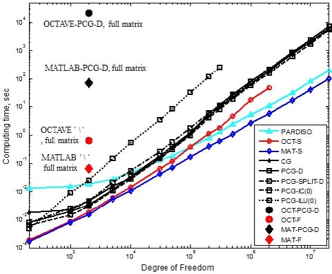
Comparison of computing time according to sparse solvers for SPD matrix, marker-line: Δ-: PARDISO, O-: OCT-S ‘\’, ◇-: MAT-S ‘\’, +-: CG, □-: PCG-D, □--: PCG-split-D., □-.: PCG-IC( 0), □▫▫: PCG-ILU(0), ●: OCTAVE®-PCG-D, full matrix solver, ●: OCTAVE® ‘\’ -full matrix solver, ◆: MATLAB®-PCG-D, full matrix solver, ◆: MATLAB® ‘\’ -full matrix solver, range: 200 DOF ~ 20 000 000 DOF (Unit: sec)
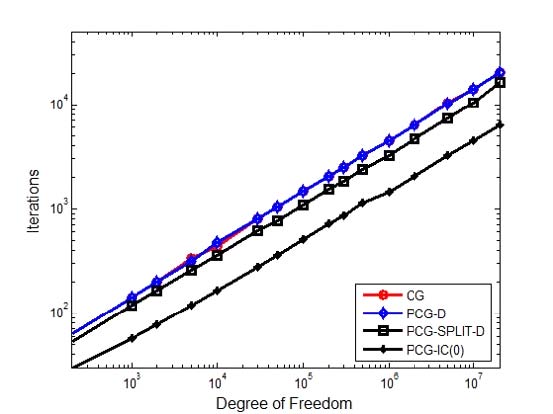
Comparison of iterations according to sparse solvers for SPD matrix, marker-line: O-: CG , ◇-: PCG-D, □-: PCG-split-D, +-: PCG-IC(0), range: 200 DOF ~ 20 000 000 DOF, (Unit: number)
On the other hand, when the coefficient matrix A was a general matrix, a preconditioner was obtained with incomplete LU factorization instead of incomplete Cholesky decomposition. Split GMRES using L and U as preconditioners in GMRES instead of PCG was most effective when the coefficient matrix A was nearly symmetric and was not effective from using preconditioner M = LU in other cases(21). In this paper, GMRES was applied to FEM data, which showed that it was inferior to PCG-D or PCG-split-D in terms of calculation speed. Especially, when using FEM data, it showed a tendency to diverge above 1323 DOF (Ex1 model). FGMRES (RCI Flexible Generalized Minimal RESidual method with ILUT Preconditioner)(26) and MGMRES(restarted GMRES) suggested by Burkardt(27) were less likely to diverge than GMRES. However, according to the characteristics of the coefficient matrix A, the user had to determine the inner loop and the outer loop number in advance, and the divergence or convergence was determined according to these values. Also, if the number of inner loop was large, the solution converged rapidly but the memory to be memorized increased and the memory efficiency decreased. Here, interestingly, Saad(21) described the difference in computational complexity in PCG when choosing preconditioner using incomplete Cholesky decomposition for SPD matrix. In this paper, we showed that the PCG could also be applied to non-SPD matrices and the same description applied to the SPD matrix when we adopted diagonal preconditioner or split diagonal preconditioner and it could be especially emphasized to non-SPD coefficient matrix. The PCG method with incomplete Cholesky decomposition preconditioner was known to apply only to SPD matrix(28). If the coefficient matrix was non-SPD matrix, Cholesky decomposition could not be applied; instead, LU decomposition applicable to a general matrix could be applied. The PCG-IC(0) could be applied only when the coefficient matrix was SPD, so it could not be applied to the FEM system matrix equation applied the actual boundary condition as in Fig. 8.
In Table 5 (1323 DOF ~ 59 643 DOF), the PCD-IC(0) could not be applied because the matrix was non- SPD. In order to solve the general matrix in the PCG method, the preconditioner could be obtained by incomplete LU decomposition instead of incomplete Cholesky decomposition. We could use PCG-ILU(0), which used L and U obtained by incomplete LU decomposition with no fillin as the preconditioner, to perform the same size LU decomposition using the coefficient matrix A. The preconditioner ILU(0) was efficient in terms of memory because the size and position of the matrix were the same as the coefficient matrix A, but there was a restriction on its use because it tended to diverge. In case of non-SPD coefficient matrix as in Fig. 12, PCG-ILU(0) showed divergence when the size of the matrix was larger than 1323 DOF. As an alternative, we could use PCGILU(τ) by obtaining L and U with Crout incomplete LU decomposition. However, the size of L and U obtained by Crout incomplete LU decomposition was large, which was not useful in terms of memory. The Crout method could be used to solve the ILU when using the Crout ILU method. However, when the Crout method was used to obtain the preconditioner LU, it showed NNZ (ILU(τ)) >> NNZ(A) (Table 7). Therefore, it could not be applied to a large size non- SPD coefficient matrix. On the other hand, as shown in the appendix, PCG-D or PCG-split-D could perform very fast convergences if coefficient matrix A was not asymmetric. In Fig. 12, the full matrix direct solver DGESV (marker: red ▼) was 1218 sec and the MATLAB® ‘\’ -full matrix solver (marker: blue ◆) was 3443 sec in the case of 59 643 DOF.

Comparison of number of non-zero of coefficient matrix A, incomplete LU with no fillin (ILU(0)) and incomplete LU with Crout ILU(τ), τ: drop tolerance, τ=10-9
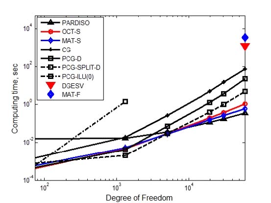
Comparison of computing time using sparse solvers for non-SPD matrix, marker-line: Δ-: PARDISO, O-: OCTAVE® ‘\’, ◇-: MATLAB® ‘\’, +-: CG, □-: PCG-D, □--: PCG-split-D., □▫▫: PCG-ILU(0), ◆: MATLAB® ‘\’ - full matrix solver, ▼: DGESV-full matrix solver, range: 75 DOF ~ 59 643 DOF (Unit: sec)
The MATLAB® sparse matrix solver ‘\’ (marker: blue -◇-) was 0.592 sec. Therefore, when using the MATLAB® operator ‘\’, computing time ratio of the full matrix solver / sparse matrix solver = 5816 times. That is, the sparse MATLAB® solver was about six thousand times faster than the full matrix MATLAB® solver.
Ratio of number of iterations in the sparse PCG method was PCD-D / PCD-split-D = 1.4 in the SPD matrix (Fig. 11). When the coefficient of the matrix was non-SPD (Fig. 13), it showed ratio of number of iterations of PCD-D / PCD-split-D = 4 and the convergence speed of PCG-split-D was 4 times faster than PCG-D. That is, in the case of the asymmetric matrix, PCG-split-D showed shorter computation time than PCG-D. The PCG-split-D, 4.805 sec, was 4.7 times faster than the PCG-D, 22.792 sec, in the case of the 59 643 DOF, where the coefficient matrix was a little asymmetric matrix (Fig. 12). When the coefficient matrix was SPD (Fig. 10), PCG-split- D was compared with 40% faster than PCG-D. In sparse solvers, the speed of calculation depended on the non-zero number of the coefficient matrix and the non-SPD matrix, not on the size of the matrix. In Fig. 14, it was compared the computing times according to NNZ of SPD and non-SPD coefficient matrices. In SPD coefficient matrix 20 000 000 DOF, PARDISO (mark: ▼) and MATLAB® sparse ‘\’ (mark: ▲) solvers showed 193 sec and 98 sec, respectively. Using the FEM stiffness matrix, non-SPD matrix, for example, Ex5 (59 643 DOF, NNZ = 1 564 440), system equation was solved by PCG-split-D, resulting in 4.805 sec, which was nearly equivalent time to solve 200,000 DOF SPD matrix (#9) problem. In other words, the sparse solver was not dependent on the size of the coefficient matrix A but on the number of non-zero of the coefficient matrix A. When NNZ was the same, SPD matrix converged faster than the non-SPD matrix in CG method and PCGD converges equally to SPD or non- SPD matrix. However, in case of equal NNZs of coefficient matrices, it showed that PCG-split-D showed faster convergence in non-SPD matrices than SPD ones.
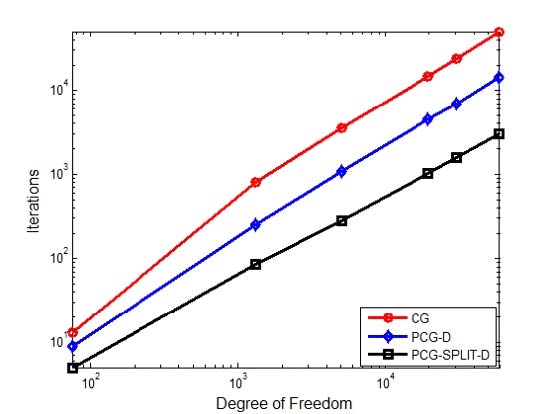
Comparison of iterations using sparse solvers for non-SPD matrix, marker-line: O-: CG, ◇-: PCG-D, □-: PCG-split-D, range: 75 DOF ~ 59 643 DOF, (Unit: number)
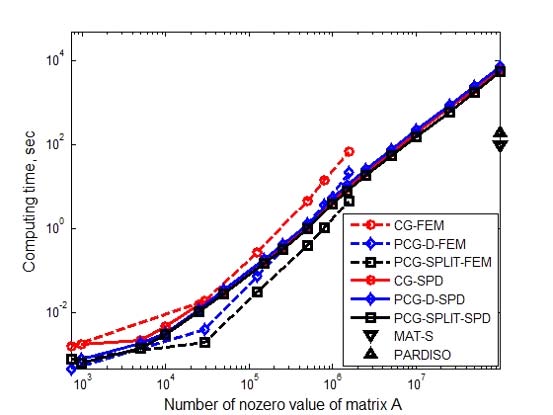
Comparison of computing time according to NNZ of sparse solvers for SPD and non-SPD matrix, marker-line: O-: CG-SPD, ◇-: PCG-DSPD, □-: PCG-split-D-SPD, O--: CG-FEM, ◇--: PCG-D-FEM, □--: PCG-split-D-FEM, range: 200 DOF ~ 20 000 000 DOF (Unit: sec)
The NNZ of the non-SPD matrix Ex5 (59 643 DOF, NNZ: 1 564 440) was equal to the NNZ of SPD matrix #10 (300 000 DOF, NNZ: 1 498 902). However, the time required for calculating using Ex5 using PCG-split-D was equal to the time for solving #9 (200 000 DOF, NNZ: 999 104). The reason why was that the number of iterations when using PCG-split-D for SPD matrix #9 and #10 was 1533 and 1846, respectively. However, when applying PCG-split-D to non-SPD matrix Ex5, the number of iterations was 2929. The non-SPD matrix Ex5 showed 48 828 and 14 475 iterations, respectively, when CG or PCG-D was used to solve system equation. Consequently, the computing time was the shortest since the number of iterations was smaller than CG or PCG-D when solving non- SPD matrix Ex5 with PCG-split-D.
6. Conclusions
(1) In this paper, we proposed physical coordinated based 3-node triangular FE, 4-node rectangular FE, and 4-node quadrilateral FE codes according to the Kirchhoff thin plate theory.
(2) FE codes using isoparametric quadrilateral FE and 3-D plate shell FE elements based on the Mindlin- Reissner thick plate theory were also presented.
(3) We found that there would be some errors in the FE codes presented by Semie(5) through validation test using a three-node triangular FE codes developed in this paper.
(4) The displacements were compared at the center point of a square plate with four sides fixed and under constant pressure. Three FE codes, which were physical coordinated based 3-node triangular FE, 4- node rectangular FE, and 4-node quadrilateral FE program developed based on the Kirchhoff plate theory, showed within a deviation of 0.9% from the theoretical value obtained by the Levy method. Therefore, three developed FEM codes were proved to be adequate to use.
(5) We also presented results using natural coordinates based isoparametric quadrilateral FE and 3-D plate shell FE codes based on the Mindlin-Reissner thick plate theory. The displacement was greater than 8 % of the value obtained by the Kirchhoff thin plate theory. The commercial software LISA analysis results were also compared and it was 16% higher than Kirchhoff’s theory without taking shear strain into account.
(6) The coefficient matrix from the actual FEM analysis was a non-SPD matrix. In case of 59 643 DOF non-SPD coefficient matrix, it showed that the calculation time was 1218 sec of the MKL library full- matrix direct solver DGESV, 4.805 sec in sparse PCG-split-D and 0.590 sec in sparse MATLAB ‘\’, respectively, indicating that the sparse solvers were superior to the full matrix solvers. Especially, sparse PARDISO took 0.345 sec.
(7)Sparse solvers showed excellent memory saving and computation speed when coefficient matrix was sparse when solving large system equations.
(8)FGMRES and MGMRES were less likely to diverge than GMRES when solving system equations with non-SPD coefficient matrix. However, according to the characteristics of the coefficient matrix, the number of inner loop and the number of outer loop must be predetermined by the user, and divergence or convergence was determined according to these values. Also, if the iteration number of inner loop was large, the solution vector converged rapidly but the memory to be memorized increased and the memory efficiency decreased. Calculation time was needed more than sparse PCG-D or PCG-split-D.
(9)In the case of the SPD coefficient matrix, the calculation performance of PCG-D and PCG-split-D was similar, but in the case of non-SPD coefficient matrix, PCG-split-D showed faster computation time than PCG-D. In the non-SPD matrix, 59643DOF, PCG-split-D was five times faster than PCG-D due to faster convergence.
(10)OCTAVE® showed that reading data files was very slower than in MATLAB® or FORTRAN.
(11)It showed that PCG-D and PCG-split-D almost were required the same calculation amount per iteration to solve system equations with SPD coefficient matrix.
(12)If the coefficient matrix was asymmetric, it showed that it may be happened to inaccurate results or divergency in PCG-D, PCG-split-D and PCGILU(0). The PCG-ILU(τ) using Crout ILU was accurate, but required more memory than ILU(0), which may not be suitable for large-size problem.
(13)Sparse solver was not dependent on the size of the coefficient matrix A but on the number of non-zero of the coefficient matrix A.
(14)In case of system equation with large non-SPD coefficient matrices, it showed that computing times were ordered with PARDISO, MATLAB® sparse operator ‘\’ and sparse PCG-split-D in short time order. But, in case of large SPD matrix, for example, 20000000DOF, sparse MATLAB® ‘\’, PARDISO, and sparse PCG-split-D exhibited 98sec, 193sec, and 5632sec, respectively.
References
- Holmström, F., (2001), Structure-acoustic Analysis Using BEM-FEM implementation in MATLAB, M.S. Thesis, Lund University, Lund, Sweden.
- Irvine, T., (2011), Plate Bending Frequencies via the Finite Element Method with Rectangular Elements, Revision A.
- Irvine, T., (2011), The Natural Frequency of a Rectangular Plate with Fixed-free-fixed-free Boundary Conditions.
- Irvine, T., (2011), The Natural Frequency of a Rectangular Plate with Fixed-fixed-fixed-fixed-fixed Boundary Conditions Revision B.
- Semie, A. G., (2010), Numerical Modelling of Thin Plates Using the Finite Element Method, M.S. Thesis, Addis Ababa University, Addis Ababa, Ethiopia.
- Ferreira, A. J. M., (2009), MATLAB Codes for Finite Element Analysis, New York, NY, Springer.
- Kwon, Y. W., and Bang, H., (2000), The Finite Element Method Using MATLAB, 2nd edition, Boca Raton, FL, CRC Press.
- Timoshenko, S. P., and Woinowsky-Krieger, S., (1989), Theory of Plates and Shells, New York, NY, McGraw-Hill.
-
Batoz, J.-L., Bathe, K.-J., and Ho, L.-W., (1980), A Study of Three-node Triangular Plate Bending Elements, International Journal for Numerical Methods in Engineering, 15(12), p1771-1812.
[https://doi.org/10.1002/nme.1620151205]

-
Batoz, J. L., and Tahar, M. B., (1982), Evaluation of a New Quadrilateral Thin Plate Bending Element, International Journal for Numerical Methods in Engineering, 18(11), p1655-1677.
[https://doi.org/10.1002/nme.1620181106]

- Bischoff, M., (2008), Modeling of Shells with Three-dimensional Finite Elements, Proceedings of the 6th International Conference on Computation of Shell and. Spatial Structures, p12-15.
-
Petyt, M., (1990), Introduction to Finite Element Vibration Analysis, Cambridge, England, Cambridge University Press.
[https://doi.org/10.1017/cbo9780511761195]

- Reddy, J. N., (1997), Mechanics of Laminated Composite Plates, New York, NY, CRC Press.
- Knight Jr., N. F., (1997), Raasch Challenge for Shell Elements, AIAA Journal, 35(2), p375-381.
- Burden, R. L., and Fairs, J. D., (2011), Numerical Analysis, 9th edition, Pacific Grove, CA, Brooks/Cole.
- Du, L., and Liu, S., (2015), Study on Preconditioned Conjugate Gradient Methods for Solving Large Sparse Matrix in CSR Format.
- Burgerscentrum, J. M., (2012), Iterative Solution Methods.
- Nikishkov, G. P., (2004), Introduction to the Finite Element Method (Lecture Notes), Aizu-Wakamatsu, Japan, University of Aizu.
- Intel, (2014), Intel® Math Kernel Library (Version 11.2) Reference Manual.
- Frydendall, J., (2009), A Parallel Implementation of a Finite Element Solver, IMM-Technical Report-2009-10, Lyngby, Denmark, DTU Informatics.
-
Saad, Y., (2003), Iterative Methods for Sparse Linear Systems, 2nd edition, Philadelphia, PA, Society for Industrial and Applied Mathematics.
[https://doi.org/10.1137/1.9780898718003]

- Schenk, O., and Gärtner, K., (2018), Parallel Sparse Direct and Multi-recursive Iterative Linear Solvers User’s Guide Version 6.1.0.
- Shenk, O., and Gärtner, K., (2003), Solving Unsymmetric Sparse Systems of Linear Equations with PARDISO, Preprint Submitted to Elsevier preprint.
- W. Layton, and M. Sussman, (2014), Numerical Linear Algebra, Morrisville, NC, Lulu Press.
- Stahel, A., (2014), Numerical Methods.
- http://sep.stanford.edu/sep/claudio/Research/Prst_ExpRefl/ShtPSPI/intel/mkl/10.0.3.020/examples/solver/source/dcsrilut_exampl2.f, .
- Burkardt, J., (2019), MGMRES: Restarted GMRES Solver for Sparse Linear Systems, https://people.sc.fsu.edu/~jburkardt/m_src/mgmres/mgmres.html.
- Mathworks, (2018), pcg (Preconditioned Conjugate Gradients Method), https://kr.mathworks.com/help/matlab/ref/pcg.html#f93-998415.
Appendix
A study on the applicability of PCG method by the asymmetry of coefficient matrix in system equation
We applied PCG method to SPD coefficient matrix #1~#16 (Table 4, Fig. 10) and non-SPD matrix Ex1~Ex5 (Table 5, Fig. 12) similar to symmetric matrix as a whole. And we got solutions within an acceptable accuracy. However, CG or PCG methods should be used with caution when solving system equations with non-SPD matrices other than SPD matrices. We investigated two examples like as followed.
Example 1: In the system equation, Ax=b, if the coefficient matrix A is a general matrix with strong asymmetry.
CG, PCG with ILU(0) or PCG with diagonal preconditioner (PCG-D) and PCG with split diagonal preconditioner (PCG-split-D) showed incorrect results but only PCG with Crout version showed correct results (Table A1).
Example 2: If the coefficient matrix is not asymmetric in the system equation Ax=b,
CG only showed the wrong results (TableA1).

Seok-Tae Park, B.S. in Hanyang University, Mechanical Eng., 1984., M.S. in KAIST, Mechanical Eng., 1986., Ph.D. in Ajou University, Systems Eng., 1999. 1986 ~ 1989., KAIST (KIST) Mechanical Eng., researcher. 1989 ~ 1992., Ssangyong Motor Co., senior researcher. 1993 ~ 1999., IAE Automotive Technical Lab. principal researcher. 2000 ~ present, in Chungbuk Health & Science University Assistant Professor. His principal interest is the fields of sound quality index codes programming, noise control, and subjective evaluation, loudspeaker, horn and microspeaker system analysis and design, boundary integral analysis in Acoustics.
