신호처리를 이용한 노크센서의 엔진진동 측정에 대한 연구
© The Korean Society for Noise and Vibration Engineering
Abstract
To measure engine vibrations, an additional accelerometer must be installed. However, selecting the measurement position is difficult to and requires additional cost. In contrast, the knock sensor is a sensor that detects the knocking of the engine. It has a piezo resistor, which is inserted in the knock sensor, that can turn these vibrations into voltage. In this study, we measured engine vibrations by using the knock sensor. The acceleration sensor and the knock sensor were simultaneously mounted and used to measure the engine vibrations. The measured signals were compared via signal processing to investigate whether the knock sensor can be a possible alternative to the accelerometer for engine vibration measurement.
Keywords:
Knock Senser, Accelero-meter, Analysis, Fast Fourier Transform, Engine Vibration키워드:
노크센서, 가속도계, 분석, 고속 푸리에 변환, 엔진 진동1. 서 론
엔진 진동을 측정하는 실험은 가속도계를 장착하는 방식으로 진행해왔다(1 ~ 3). 이는 추가적인 비용과 더불어 다량의 기계가 조립되어 폭발로 인한 진동 발생을 갖는 엔진의 특성상 측정 위치를 특정하기가 매우 어렵다.
한편 기존의 엔진에 장착된 노크센서는 엔진에서 발생되는 진동을 계측하여 엔진 ECU가 점화시기를 제어할 수 있는 입력신호로 활용된다(4). 따라서 이 신호를 이용해 엔진의 진동을 평가할 수 있다면 편리성과 함께 경제적인 측면에서 큰 장점이 될 수 있다(5). 이와 유사한 최근연구로써 S.Vulli.는 STFT 처리기법을 이용해 노크센서에서 계측되는 진동신호에서의 부분진동(흡배기밸브의 작동 충격파, 연소압력에 따른 진동 등)에 대한 원인을 규명하는 데 집중했으나 노크센서를 이용한 진동측정 방법에 대한 직접적인 언급은 없었다(5). 따라서 이 논문은 가속도계를 대신하여 노크센서를 이용해 엔진의 진동을 계측할 수 있는 방법을 제시하기 위한 연구로써 정상진동을 갖는 엔진의 공회전 상황에서 노크센서를 통해 계측되는 진동신호를 FFT변환 후 시간영역 해석기법을 통해 분석하는 방법을 사용한다(6). 또한 이에 대한 검증을 위해 동일한 조건에서 가속도계를 장착하여 진동을 측정 후 동일한 기법으로 신호처리를 하여 전술한 실험과 비교 후 고찰한다.
2. 실 험
2.1 실험내용 및 방법
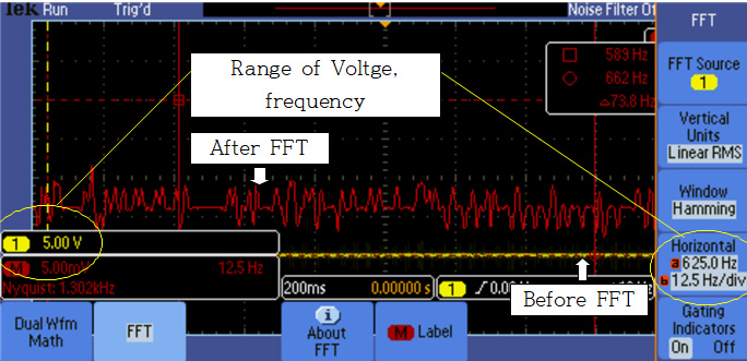
노크센서는 진동에 비례한 전압을 출력함으로 oscilloscope를 이용하여 측정한다. 4실린더 기관의 평균진동주파수 20 Hz ~ 30 Hz를 고려해 oscilloscope 상의 horizontal level range는 12.5 Hz/div ~ 625.0 Hz/div로 설정한다. 또한 knock sense의 신호선(2번 pin) ECU로부터 5V reference전압을 공급받고 있음으로 voltage level range는 3V 이하로 설정하며 측정된 진동에 대한 정확한 분석을 위해 FFT변환을 실시한다(Fig. 1). 또한 진동신호에 대한 정량적 분석을 위한 신호처리를 위해 주파수 신호의 magnitude를 EXCEL 프로그래밍으로 변환하여 시간영역 해석기법인 RMS, peak to peak, crest factor의 신호처리 과정을 거쳐 진동의 경향을 분석한다. 상기 실험에 대한 검증을 위해 intakr-manifolder 중심에 가속도계를 설치하고 측정된 시간에 따른 가속도 변화를 FFT를 통해 측정 후 전술한 방법으로 신호처리하여 비교 후 고찰한다.
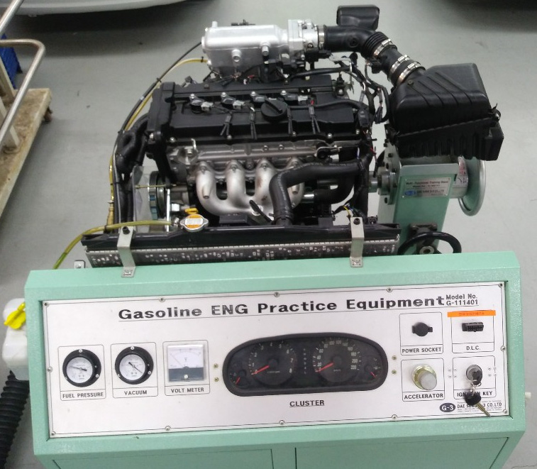
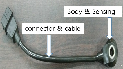
실험 대상 엔진은 아반뗴 XD에 장착된 알파 엔진 1600cc 시뮬레이션(Fig. 2),(Table 1)으로 주행거리는 약 60000km이며, EMS(engine management system)와 노크센서(Fig. 3)는 KEFICO社의 제품으로 가솔린을 연료로 하며 엔진의 형식은 I-TYPE의 DOHC(double overhead camshaft)를 이용한다. 수냉식 기관으로 실린더는 4개이며 점화순서는 순차적으로 점화되는 방식을 사용하고 있다.
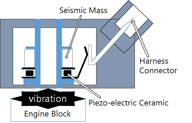
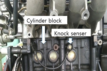
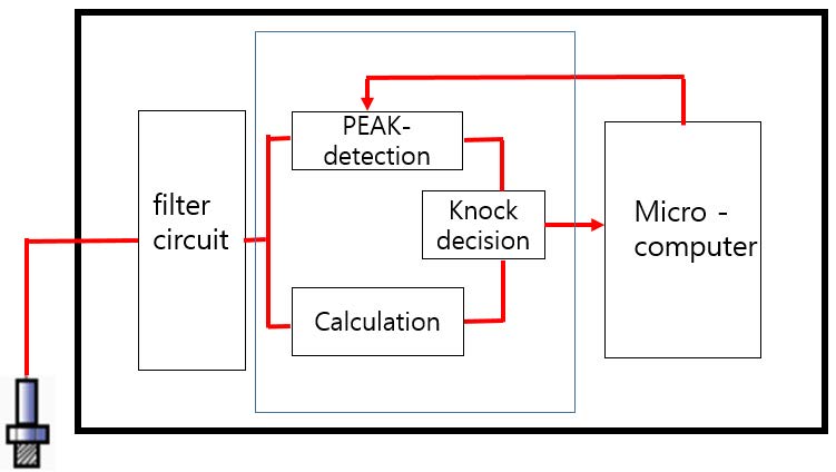
노크센서는 엔진의 블록(Fig. 5)에 장착되어 연소 시 발생되는 진동을 측정하는 역할을 한다. 내부에는 piezo를 장착하여(Fig. 4) 진동발생과 비례하여 전압을 출력하게 되고 이를 ECU에 전달하면 이중 노킹에 해당하는 특정 고주파(8kHz ~ 16kHz) 성분만 필터링하여 점화시기를 제어하는 데 사용하고(Fig. 6) 나머지 진동은 무시한다.
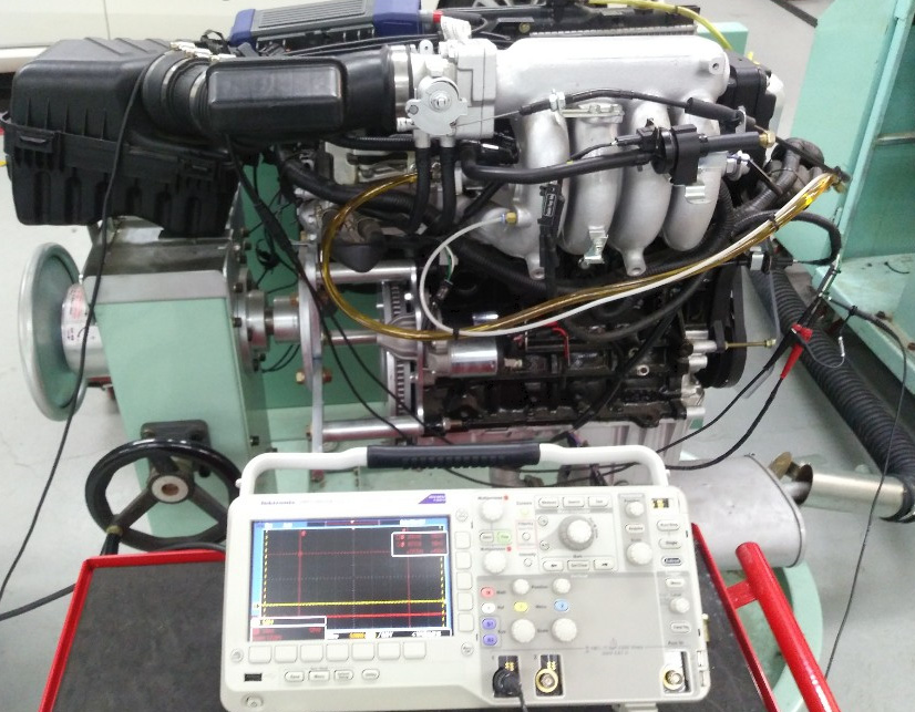
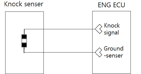
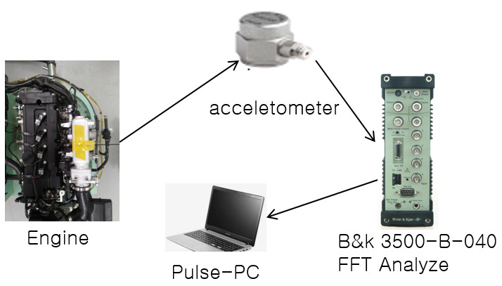
노크센서 전달되는 진동을 측정하기 위하여 Fig. 7과 같이 실험장치를 구성하였다. 실험장비로는 Tektronix社의 DPO2022B oscilloscope를사용하였다. 노크센서를 통해 입력되는 신호 중 주파수분석을 위한 FFT변환이 가능한 장비로써 Fig. 8의 노크센서 회로도상의 신호선(knock signal)과 접지선(ground senser)에 해당하는 부위에 측정 프로브를 설정하였다. 또한 실험결과에 대한 검증을 위해 가속도계(ENDEVCD 27AM1-100)를 설치하고 측정된 시간에 따른 가속도 변화를 FFT analyzer (B&K 3560-B-040)를 통해 변환한다(Fig. 9).
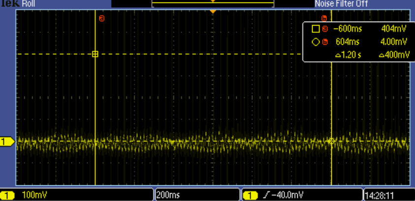
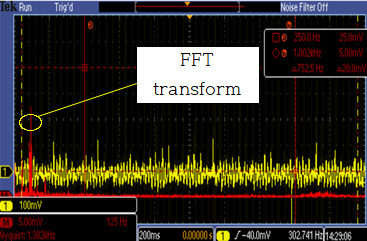
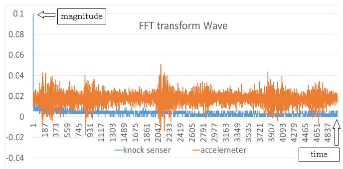
노크센서에서 계측되는 공회전 진동에 따른 출력전압은 4.00 mV ~ 404 mV까지 출력되었고(Fig. 10) 이를 FFT변환을 한 결과 250.0 Hz ~ 1.002kHz의 주파수 레인지를 가지고 있음을 확인하였다(Fig. 11). 이는 엔진내부의 밸브 및 각종 보기류의 추가적인 진동 주파수가 포함되어 일반 주파수보다 높은 범위를 나타냄을 알 수 있었다. FFT과정을 거쳐 엑셀 프로그래밍으로 PLOT한 2가지 신호를 (Fig. 12)에 나타내었다. 가속도센서는 일반적으로 동일한 조건에서 진동을 받아들였을 때 내부의 AMP를 통해 신호를 증폭하여 진동 변화의 경향을 잘 파악할 수 있음을 알 수 있었다.
이와 비교하여 노크센서의 진동폭은 변화가 적음을 알 수 있는데 이는 knock window가 약 8kHz ~ 16kHz의 고주파에서 발생되기 때문에 이에 최적화된 센서특성상 저주파대역(8kHz 이하)은 상대적으로 감지하는 능력이 떨어짐을 알 수 있었다. 따라서 저주파영역에서의 진동경향 분석을 위해 텍스트로 변환 (Table 2) 후 시간영역의 해석기법을 이용해 RMS, peak to peak, crest factor에 대한 계산을 하였고 가속도계를 이용한 실험 역시 동일한 신호처리를 통해 도출된 수치를 Table 3에 나타내었다. 그 결과 peak to peak, crest factor의 경우는 약 25 % 범위의 비교적 낮은 일치율을 보였으나 RMS의 정확도는 98.43 %로 높은 일치율을 보였다. 따라서 정량적인 엔진진동을 측정하고 분석할 때 노크센서를 활용할 수 있는 가능성을 확인하였다.
3. 결론 및 향후과제
이 실험을 통해 노크센서를 이용하여 엔진진동을 계측하는 방법에 있어서 시간영역의 해석기법인 RMS를 활용하는 것이 신뢰도가 높음을 확인하였고, 이를 통해 진동의 정량적인 관점에서 계측하고 분석할 때 유용할 것으로 판단된다. 또한 peak to peak, crest factor는 상대적으로 신뢰도가 떨어져 RMS에 비해 유용하지 못함을 확인하였다.
향후 연구의 영역을 보다 확장하여 노크센서를 이용한 비정상 엔진진동 발생시 RMS 추이를 관찰하는 연구를 진행할 예정이다.
References
-
Moosavian, A., Najafi, G., Nadimi, H., and Arab, M., (2017), Estimation of Engine Friction Using Vibration Analysis and Artificial Neural Network, 2017 International Conference on Mechanical, System and Control Engineering (ICMSC), p130-135.
[https://doi.org/10.1109/icmsc.2017.7959457]

-
Çalık, A., (2018), Determination of Vibration Characteristics of a Compression Ignition Engine Operated by Hydrogen Enriched Diesel and Biodiesel Fuels, Fuel, 230, p355-358.
[https://doi.org/10.1016/j.fuel.2018.05.053]

-
Mao, Z., Jiang, Z., Zhao, H., and Zhang, J., (2018), Vibration-based Fault Diagnosis Method for Conrod Small-end Bearing Knock in Internal Combustion Engines, INSIGHT, 60(8), p418-425.
[https://doi.org/10.1784/insi.2018.60.8.418]

- Yang, H. S., Lim, J. H., and Chun, D. J., (2008), A Study on Characteristics of Knocking in Gasoline Engine through ECU Control, Journal of Korea Safety Management & Science, 10(3), p109-115.
- Vulli, S., Dunne, J. F., Potenza, R., Richardson, D., and King, P., Time-frequency Analysis of Single-point Engine-block Vibration Measurements for Multiple Excitation-event Identification, Journal of Sound and Vibration, 321(3-5), p1129-1143.
- Kim, Y. H., (2010), The Study on the Test on Initial Abnormal Engine through Processing Signal, Hayang University.
-
Barelli, L., Bidini, G., Buratti, C., and Mariani, R., (2009), Diagnosis of Internal Combustion Engine through Vibration and Acoustic Pressure Non-intrusive Measurements, Applied Thermal Engineering, 29(8-9), p1707-1713.
[https://doi.org/10.1016/j.applthermaleng.2008.07.025]

-
Jeong, T. S., and Singh, R., (2000), Analytical Methods of Decoupling the Automotive Engine Torque Roll Axis, Journal of Sound and Vibration, 234(1), p85-114.
[https://doi.org/10.1006/jsvi.1999.2860]


Young Hyun Kim received the M.S. degree in Mechanical Engineering department at Hayang University in 2010. He has a certification as a Professional Engineer Transportation Vehicles and Master Craftsman Motor Vehicles Maintenance. He worked at Hyundai Motor Company from 2003 to 2014. Currently, he is working as a assistant professor at Korea Polytechnic Colleges.

Dae Cheol Ko received the Ph.D. in department of mechanical design engineering at Pusan National University in 1998. His main research interest is to develop a novel manufacturing process of lightweight component in automobile and aerospace. He is working as a professor at Pusan National University since 2007.
