프로펠러 가진에 의한 저속 디젤엔진을 갖는 추진축계의 종진동
‡ Recommended by Editor Jun Hong Park
© The Korean Society for Noise and Vibration Engineering
Abstract
The axial vibration of propeller-induced excitation can be mostly seen in warships that have high-speed rotation propulsion shafting systems equipped with reduction gears. Coupled torsional and axial vibration is mainly focused on the excitation force that is induced by the cylinder’s gas pressure and the piston’s reciprocating mass in low-speed two-stroke diesel engines with seven or fewer cylinders; more complex vibration modes with one or more nodes can be seen in engines with eight or more cylinders. This thrust variation force caused by the axial vibration is the excitation force of the ship’s deckhouse in the longitudinal direction and has been researched extensively in the past. Recently, super-size containerships have been built that have more than 20 000 TEU. These ships have adopted low-speed diesel engines with 10 or more cylinders as their prime mover and the distance between the propeller and the main engine has increased significantly due to the streamlining of their hulls. As a result, there is the probability of resonance between the propeller’s axial excitation and the second node vibration. While this vibration frequency is rare, the possibility of resonance with the ship’s superstructure can create vibrations in the pipes and various accessories surrounding the main engine and stern tube. In addition, severe vibrations can occur if the natural frequency of these parts and that of the axial vibration are similar, which necessitates installing an additional damper on the intermediate shaft that resembles an axial vibration damper that is attached to the crankshaft free end. This paper intends to research the characteristics of axial vibration through theoretical analysis and measurement data with a focus on the 2nd order axial excitation of the propeller blade number in a propulsion shafting system with a 11G90ME engine as the research model.
Keywords:
Axial Vibration, Propeller Excitation, Propulsion Shafting System키워드:
종진동, 프로펠러 가진, 추진축계1. 서 론
프로펠러 전·후방향 가진에 의한 종진동은 감속기가 있는 추진축의 군함 등에서 프로펠러 회전수가 높은 경우에 고유진동수와 주로 프로펠러의 날개수차수의 성분이 검토 대상이었다. 저속 2행정디젤엔진을 주 기관으로 한 추진축계는 엔진의 폭발압력에 의한 기진력을 중심으로 7실린더 이하 엔진에서는 비틀림진동과 연성된 종진동이 그리고 8실린더 이상 엔진에서는 복잡한 진동모드를 갖는 0절 진동이 검토 대상으로 크랭크축 선단에 종진동 댐퍼를 부착함으로써 종진동을 방지하고 있다. 이러한 종진동에 의해서 발생하는 추력변동력은 선박의 거주구 상부의 전·후 진동을 일으키는 기진력으로 지금까지 많은 연구들이 진행되어 왔다(1~7). 최근에는 2만 TEU 이상의 초대형 컨테이너선이 등장하였다. 이러한 선박은 10실린더 이상의 대형 저속디젤엔진을 주기관으로 채택하고 후미의 날렵한 선형에 따라 프로펠러와 주기관 사이의 길이도 상대적으로 많이 길어졌다. 이 경우 프로펠러의 순수한 종방향 1절 또는 2절 진동의 고유진동수가 기존 선박에 비해 낮아지기는 하였지만, 공진차수가 높아 이 진동에 의한 문제가 발생된 사례는 보기 힘들다. 특히 진동 자체가 주기관이 아닌 선미 축을 중심으로 일어나는 진동모드와 가진 역시 주기관이 아닌 프로펠러의 가진은 해결방법은 쉽지 않다. 그리고 이 진동모드에 의한 진동이 심할 경우 선미관의 각종 장치 및 일부 주기관과 액세서리도 문제가 될 수 있다.
이 논문은 11G90ME엔진을 주기관으로 한 추진축계의 종진동을 연구 모델로 프로펠러 날개수의 2차 성분은 측정 자료를 통해서, 그리고 엔진의 종방향 기진력은 제작사에서 제공한 이론적인 가스압력을 중심으로 한 하모닉계수를 이용하여 종진동의 이론적 해석과 그 특성을 연구하고자 한다.
2. 추진축계의 종진동해석
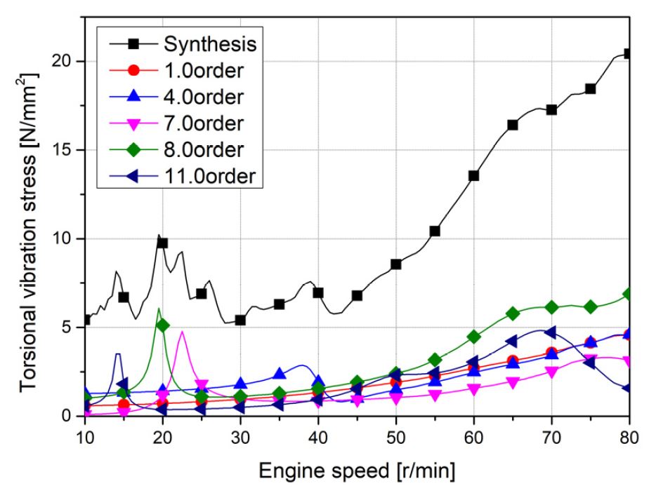
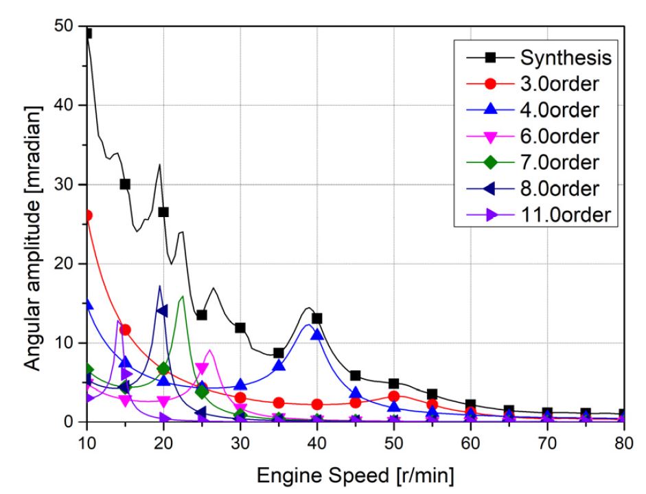
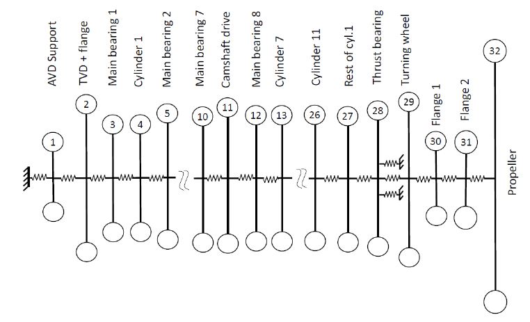
연구 대상 선박의 추진을 위한 주기관 및 프로펠러의 제원은 Table 1과 같다. 비틀림진동에 의한 종진동의 연성효과를 적용하기 위하여 비틀림진동은 19개의 집중질량을 갖는 모델로 하여 해석을 수행하였다. 비틀림진동은 2절 8차와 11차가 주이며 엔진제작사는 Table 1과 같이 32톤의 고성능 튜닝댐퍼를 2절 비틀림진동에 튜닝하도록 설계하여 부착하였다. Fig. 1은 크랭크축의 중간지점인 체인 드라이브에서 해석한 비틀림진동 응력이며 2절의 8차가 가장 크다. 중간축이나 프로펠러축의 비틀림진동 응력은 검토할 정도로 크지 않기 때문에 여기서는 제외하였다. 그리고 프로펠러의 연성효과를 확인하기 위하여 해석한 비틀림진동의 각진폭을 Fig. 2에 보인다. 여기서 엔진을 많이 사용하는 50 r/min 이상에서 상용회전수인 MCR (maximum continuos rating)까지는 각진폭이 작아서 비틀림진동에 의한 추력변동력은 발생하지 않을 것으로 예상된다. 추진축계의 종진동을 해석하기 위하여 Fig. 3과 같이 각 실린더는 2개의 집중질량으로 가정하여 총 32질점계로 나누어 해석을 수행하였다.
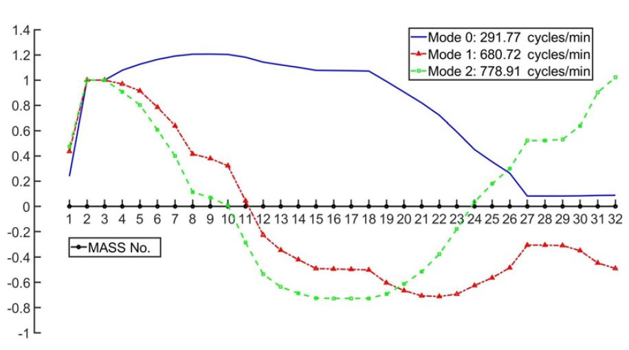
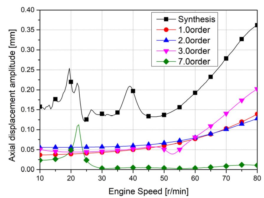
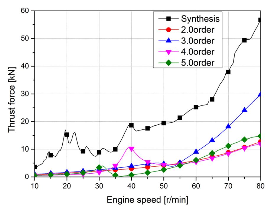
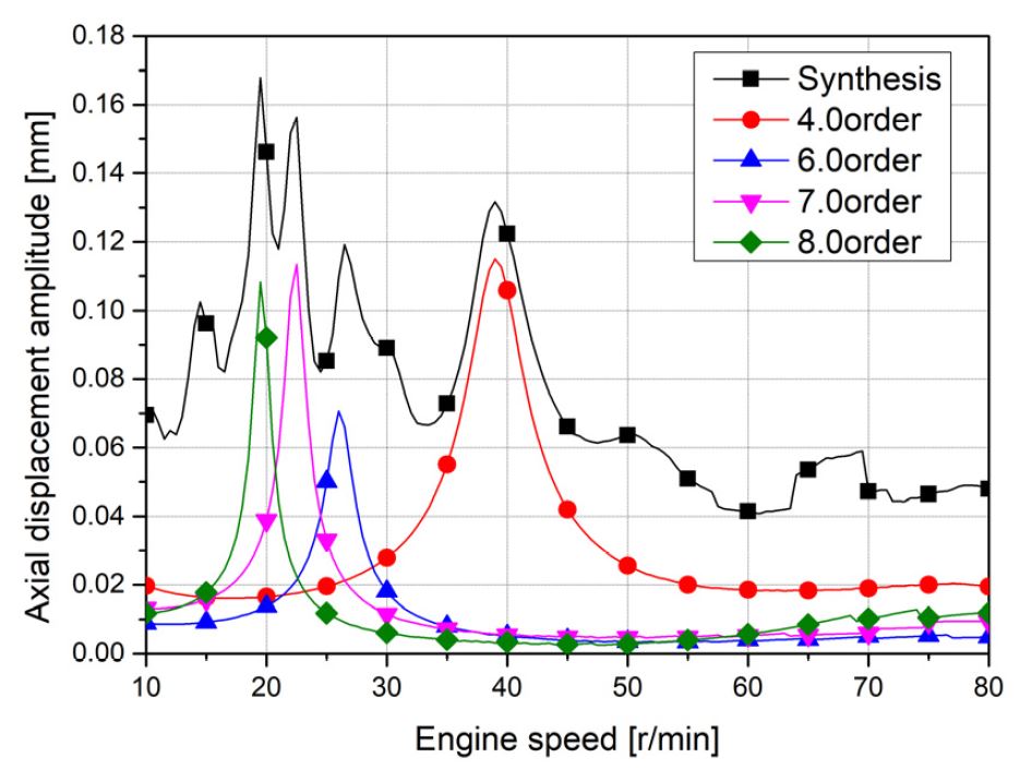
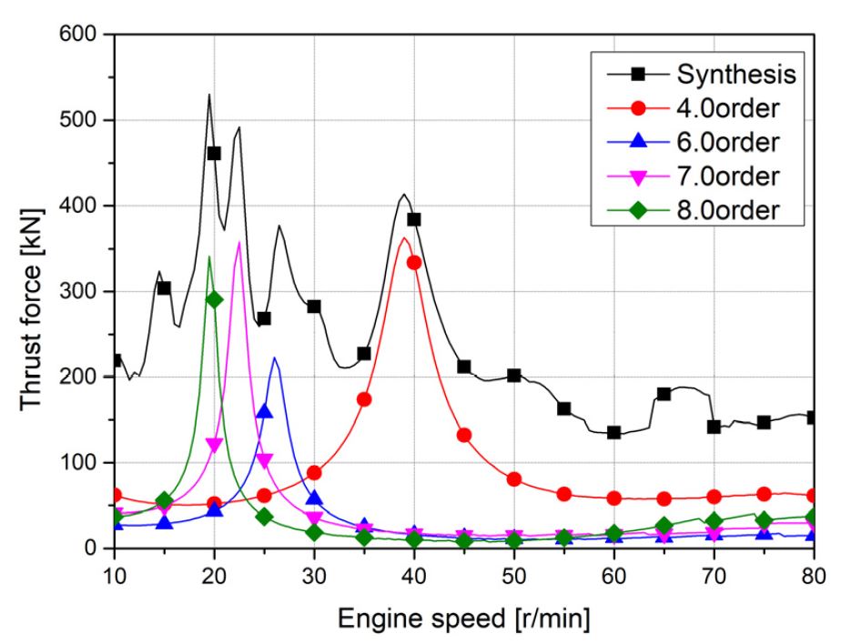
자유진동 계산을 위하여 Table 1의 종진동 댐퍼의 감쇠 값을 이용하여 감쇠(종진동 댐퍼는 제외)와 기진력을 무시하여 고유진동수와 진동모드를 구할 수 있다(7). 고유진동수에 대한 계산결과는 Table 2에 보이며, 종진동의 특성은 종진동 댐퍼와 추력베어링의 강성지지에 의해서 절점이 없는 0절 진동부터 시작한다. 여기서 종진동 댐퍼가 작동하지 않을 경우와 댐퍼의 감쇠와 각속도를 서로 곱하여 강성(감쇠×ω)으로 가정한 디튜너(de-tuner)의 계산한 결과를 보인다. 그리고 강제감쇠진동 계산은 종진동 댐퍼의 비선형성을 고려하여 전달매트릭스법을 이용하였다. Fig. 4는 진동 모드(또는 노드)를 표시한 것으로 추력베어링의 강성에 의해서 절점이 생기기 않으므로 편의상 진동 모드 0로 표시하였고, 모드 1과 모드 2는 엔진의 회전수와 비교하여 지금까지는 검토 대상이 아니었지만, 이 논문에서는 2 모드의 10차(공진점 77.8 r/min)가 검토 대상이다. Figs. 5 ~ 8은 모든 엔진제작사들이 지금까지 관행적으로 수행하는 프로펠러 기진력은 무시하고 엔진의 비틀림 및 종 기진력에 의한 해석결과이다. Fig. 5는 크랭크축 선단 종진폭이며 비교적 진동이 크지 않으며, 진폭이 적을수록 댐퍼의 감쇠는 적어지고 진폭이 크면 오히려 감쇠가 커져야 한다. Fig. 6은 종진동 댐퍼에 걸리는 추력변동력으로 4차 성분은 비틀림진동에 의한 연성 효과이다. Fig. 7은 추력베어링에 종진폭으로 모든 피크 진동은 비틀림진동에 의해서 발생한 프로펠러의 추력 변동력에 의해서 발생한 진동이다. Fig. 8은 종진폭과 추력베어링의 강성을 고려하여 추력변동력으로 환산한 결과이다. 그림에서 보는 바와 같이 엔진을 많이 사용하는 회전수 50 r/min 이상에서는 공진점이 존재하지 않고 추력변동도 크지 않다.
3. 실선 실험과 고찰
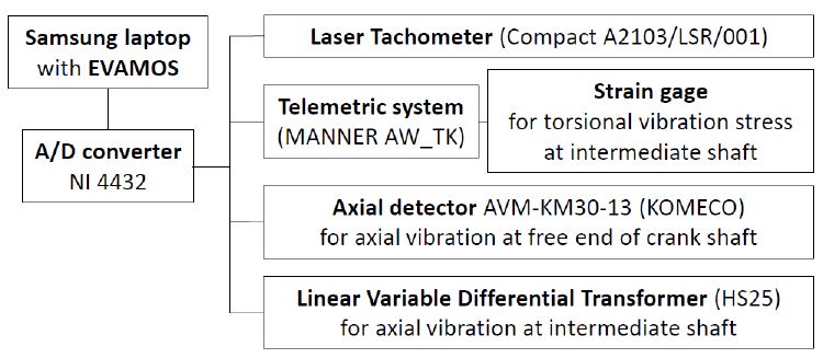
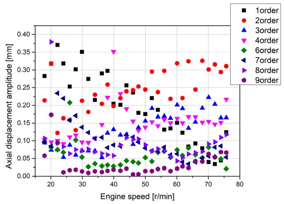
크랭크축 선단진폭은 종진동 모니터링 시스템을 이용하였고 엔진끝단인 중간축의 플랜지에서 종진폭 측정하기 LVDT(linear variable differential transducer)를 설치하였으며 전체적인 장비는 Fig. 9와 같이 배치하였다. LVDT 설치는 비틀림진동에 의한 종진동의 연성효과를 측정하기 위한 것이다. 또한 추력변동의 주원인인 비틀림진동을 측정하기 위하여 중간축에 스트레인게이지를 이용한 full bridge를 구성하여 부착하고 원격 시스템을 이용 비틀림진동을 측정하였다. 그리고 여기서 얻은 신호는 NI A/D 변환기를 이용하였고 분석 S/W는 자체 개발한 EVAMOS(8)을 이용하였다. Fig. 10은 크랭크축 선단 종진동의 계측결과이며 뚜렷하게 종진폭이 크지 않다. Fig. 5의 해석결과에서 비교하여 3차 ~ 4차는 어느 정도 비교할 수 있으나, 1차 ~ 2차 성분은 종진동보다는 런아웃(run-out)성분일 가능성이 높다. 이는 크랭크축의 총 길이가 18 m에 달하고 순수한 종진동보다는 축의 횡진동과 런아웃(run-out) 등 종진동 이외의 복잡한 크랭크축의 운동이 포함되어 있다고 볼 수 있다. 또한 4차 성분은 비틀림진동에 의한 가진된 연성 효과로 해석결과보다 높게 측정된 것은 해석 시 일률적으로 댐퍼의 감쇠가 크게 평가한 것으로 판단된다. 즉 종진폭이 적으면 감쇠가 적어지고 종진폭이 크면 감쇠가 증가한 종진동 댐퍼의 비선형성 때문인 것으로 추정할 수 있다.
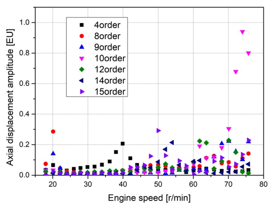
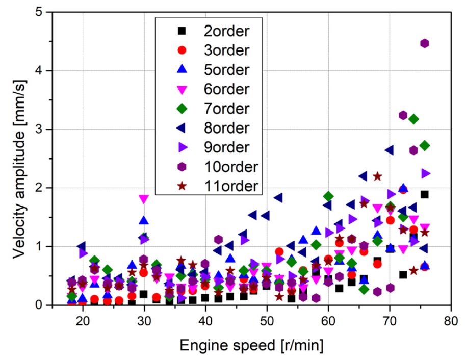
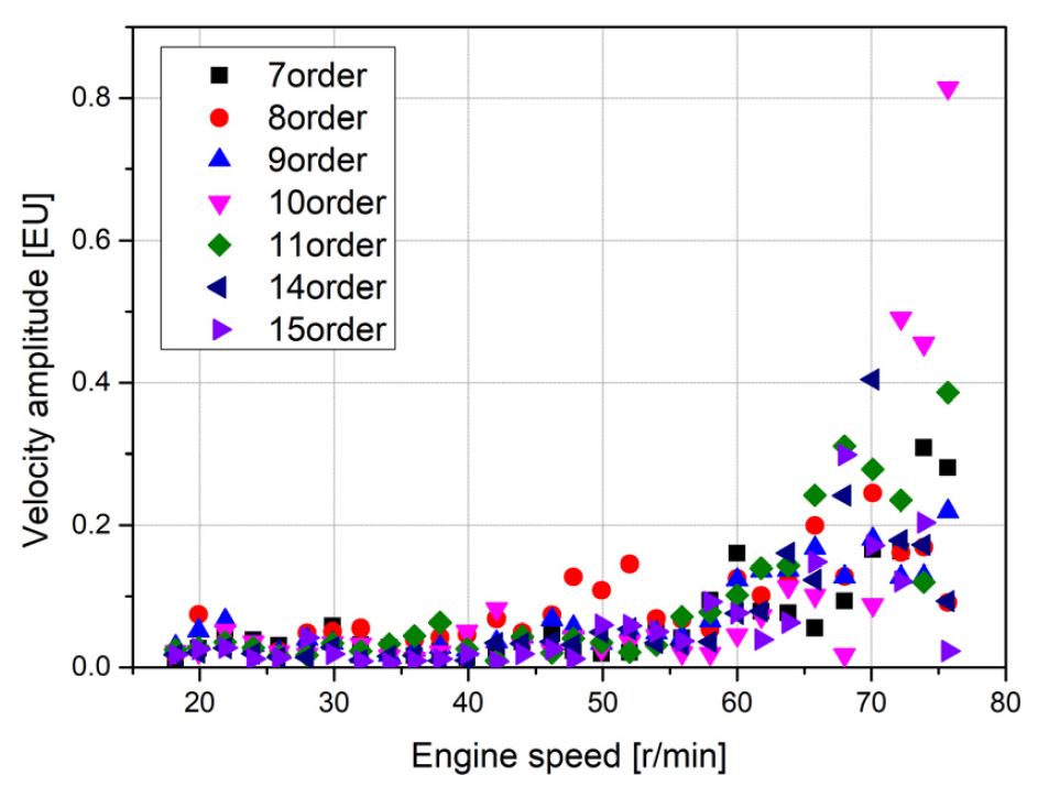
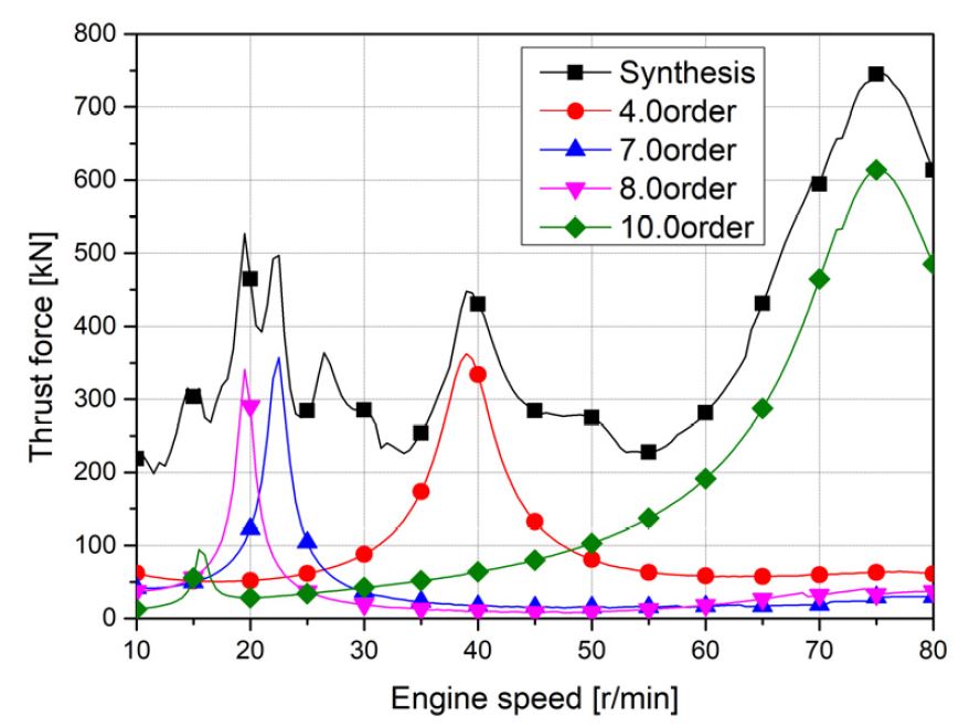
Fig. 11은 중간축 플랜지에서 측정한 종진동으로 추력베어링에서 측정한 값으로 환산하기 위해서는 Table 2와 Fig. 4를 참고하여 2절 진동모드 상 0.82배하여 사용하여야 한다. 그리고 추력변동력은 이 값에 Table 1에서 추력베어링의 강성을 곱해서 계산하게 된다. 또한 그 값을 공개하기가 곤란하여 합성된 최대 진폭을 1.0로 놓고 상대비로 환산한 결과들을 보여주고 있다. 여기서 15차의 공진은 50 r/min 그리고 10차는 74 r/min에서 일어나며 진동주파수는 12.3 Hz로 Table 2의 해석결과보다 약 0.6 Hz 낮다. 4차와 8차는 비틀림진동에 의한 연성진동이다. Fig. 12는 추력 베어링의 반대편인 주기관 앞쪽 상부에서 측정한 전후진동이다. 특히 10차 성분은 가진점인 추력베어링과 진동계측점의 사이 수평거리가 약 21 m임을 고려할 때 global한 진동으로 낮은 것은 아니다. Fig. 13은 주기관에 부착되어 있는 액세서리의 진동으로 합성된 최대진폭을 1.0으로 하여 상대 속도 진폭을 보인다. 이 결과들로부터 종진동은 크랭크축의 종진동뿐만 아니라 주기관 본체진동에 영향을 미치는 것을 확인할 수 있다. 이 실험에서는 예견되지 않은 종진동으로 인하여 선미관에서 진동측정은 못하였지만 이러한 진동이 발생할 경우 선미관의 주요 부품에 대해서도 진동을 확인하는 것이 바람직하다. Fig. 14는 해석 시 고려하지 못한 프로펠러의 순수한 추력변동의 영향을 확인하기 위하여 프로펠러 날개수의 2배수 성분을 종진폭의 측정결과와 유사하도록 이론적인 시뮬레이션을 수행하였다. 그 결과 평균추력의 2.5 %로 추정되었으며 해석한 추력베어링의 종진동 결과를 보인다. 여기서 10차 종진폭이 선단진폭에 비해 높지 않지만, Fig. 15에 보인 바와 같이 상응된 추력변동력은 600 kN로 트러스트 리버설(thrust reversal) 현상은 일어나지 않았지만 평균추력의 20 %이상으로 상당히 높은 편이다.
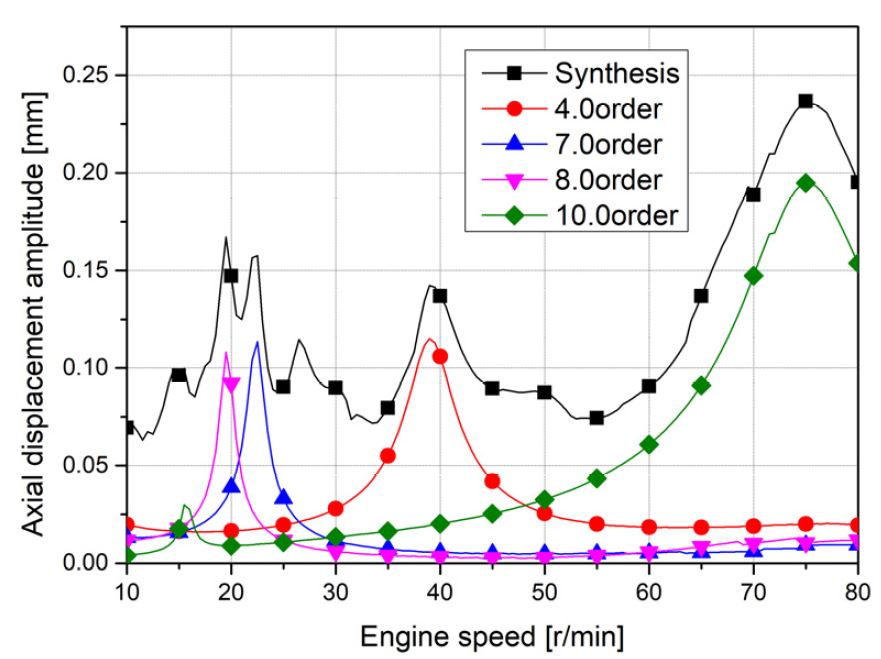
Recalculated axial displacement amplitude including the 2nd order excitation of propeller blade number at thrust bearing
4. 결 론
최근 초대형 컨테이너선 등장과 함께 추진축계의 종진동 모드는 좀 더 복잡해지고 순수한 전후방향 프로펠러 추력변동에 의해서 발생하는 종진동의 공진현상을 해석 및 계측을 통해서 확인하였다. 이 선박의 진동특성과 방진대책을 요약하면 다음과 같다.
(1) 프로펠러 날개수의 2배의 가진 추력변동력은 중간축에서 LVDT의 측정 자료를 이용 이론적인 시뮬레이션을 한 결과 평균추력의 약 2.5 %로 추정되었다. 또한 이때 추력베어링에 전달되는 힘은 공진점에서 평균추력의 약 20 %로 환산되었다. 따라서 설계 초기 이론상 이 진동이 예상되면 경험적인 요소를 검토하여 판단하여야 하겠지만, 추진축계 및 선미관 설계에 이를 충분히 고려해야한다.
(2) 종진동에 의한 추력변동력은 추력베어링을 통해 주 기관의 상부까지 전달되어 본체의 전후방향진동이 일어남을 확인하였다. 다만 고유진동수가 높아 선체 상부까지 전달되어 공진이 발생될 가능성은 낮지만 주 기관 주위의 파이프들과 각종 액세서리들의 진동에 영향을 주는 것을 확인하였다. 특히 이 부품의 고유진동수와 프로펠러 날개의 2배수 가진에 의한 종진동의 고유진동수가 유사할 경우 심한 진동을 유발할 수 있다.
(3) 프로펠러 기진력에 의한 공진에 의해서 상용운전회전수에서 발생하는 추력베어링의 추력변동력이 클 경우 선미관 특히 밀봉장치에 영향을 줄 수 있으므로 적합한 방진대책이 필요하다. 그리고 이 진동이 심할 경우 방진대책으로 공진회전수를 피해 운전하거나 크랭크 선단에 부착된 종진동 댐퍼와 유사한 댐퍼를 중간축에 추가적으로 설치할 필요가 있다.
Acknowledgments
이 연구는 산업통상자원부 소관 산업융합기반구축사업의 “중소형 선박엔진 및 관련기자재 공인시험인증센터 구축” 사업의 지원을 받아 수행되었습니다.
References
- Hylarides, S. and van Gent, W., 1979, Hydrodynamic Reactions to Propeller Vibrations, Trans. I Mar E(C), Vol. 91, Conference No. 4, Paper C37.
- Fujii, K. and Tanida, K., 1984, Exciting Forces of Ship Vibration Induced by Torsional and Longitudinal Vibration of Shafting System, International Cooperation on Marine Engineering Systems 1984, Trieste.
- Jakobsen, S. B., Bryndum, L., Fukuda, T. and Ohtsu, M., 1991, Axial Vibration of Crankshaft of Long-stroke Diesel Engine and the Control of Their Influence of Crankshaft Strength and Hull Vibration Control, 19th CIMAC Congress.
- Kikuchi, A., Makuta, H. and Yoshihara, S., 1995, Vibration Analysis of a Diesel Engine Crank Shaft System Considering Coupled Effects of Torsional and Axial Modes, 19th CIMAC Congress.
- Lee, D. C., Nam, J. G. and Ko, J. Y., 2001, A Study of Axial Vibration of Two Stroke Low Speed Diesel Engine on the Diesel Power Plant, Transactions of the Korean Society for Noise and Vibration Engineering, Vol. 11, No. 9, pp. 398~405.
- Wärtsilä, 2006, Coupled Vibration, Wärtsilä Vibration Seminar Material.
-
Song, M. H. and Lee, D. C., 2018, Axial Vibration Analysis Model and Its Vibration Characteristics on the Ultra Long Stroke Low Speed Diesel Engine A Study of Axial Vibration of Two Stroke Low Speed Diesel Engine, Transactions of the Korean Society for Noise and Vibration Engineering, Vol. 28, No. 6, pp. 635~641.
[https://doi.org/10.5050/KSNVE.2018.28.6.635]

-
Lee, D. C., Joo, K. S., Nam, T. K., Kim, E. S. and Kim, S. H., 2009, Development of Engine Vibration Analysis and Monitoring System(EVAMOS) for Marine Vessels, Transactions of the Korean Society for Noise and Vibration Engineering, Vol. 19, No. 2, pp. 155~162.
[https://doi.org/10.5050/KSNVN.2009.19.2.155]


Myeongho Song received his M. Eng. from Mokpo Maritime University in 2008. He is now working Ship Repair Supporting Center. Also he is studying Doctor course at Dynamics Lab. of Mokpo maritime university.

Donchool Lee received his Dr. Eng. from Mechanical Engineering department at Korea Maritime University in 1995. He worked at Hyundai Heavy Industries from 1983 to 1999. He is now a professor of Mokpo National Maritime University.

