에어컨 실외기 패널의 진동저감
© The Korean Society for Noise and Vibration Engineering
Abstract
In this paper, a method for improving the hardness of the mount is proposed in order to reduce the vibration of the air conditioner outdoor unit panel. First, the vibration level of the first harmonic frequency was determined, which was found to be high, that is, 600 r/min and 760 r/min. Second, the vibration shape was analyzed via an operation deflection shape (ODS) analysis, and then, a mode analysis was performed using a finite element model to analyze the influence of the local vibration of the panel. It was found that the panel vibration originated from the rigid vibration of the outdoor unit. Finally, the effect of the model in terms of reduction in the vibration was confirmed by applying a mount with an improved hardness based on the impact response spectrum. Finally, the effectiveness of the improved mount design of the air conditioner outdoor panel in reducing the vibration was verified.
Keywords:
Air Conditioner Outdoor Unit, Operating Deflection Shape, Vibration Mode Analysis, Impact Response키워드:
에어컨 실외기, 작동 중 변형 형상, 진동모드해석, 충격응답1. 서 론
최근 소비자들은 에어컨 실외기에 대한 저소음, 안정성 등의 쾌적한 환경을 요구하기 때문에 이에 만족할 수 있는 기술개발을 위한 다양한 연구가 수행되고 있다. 실외기는 팬(fan)과 모터(motor)의 구동으로 인한 진동이 브라켓(bracket)을 통해 패널(panel)로 전달되어 소음과 진동이 발생한다. 설치장소는 주로 주거지 인근인 옥상, 베란다 등에 설치되어 소비자들에게 불편함을 유발한다. 따라서 실외기의 저소음·진동에 관한 연구는 필수적이다. 실외기의 방사소음과 진동 발생현상은 크게 두 가지로 나눌 수 있다. 첫째는 유체역학적 기체소음(air-borne noise), 둘째는 구조진동음(structure-borne noise)으로 구분된다. 실외기의 유동소음의 관련된 연구로 Guedel(1)은 팬(fan)의 기하학적 특성을 개선하여 소음을 저감하였다. Lee, S. B. et al.(2,3)은 팬의 난류유동소음의 특성을 분석하고, 저소음 팬에 대한 설계를 제시하였다. 구조진동음의 관련된 연구로 Ahn, K. W. et al.(4)은 실외기 압축기(compressor)에 대한 소음원을 규명하고, 음향 인텐시티(sound intensity)를 통해 규명된 압축기 하단부의 소음원에 대하여 방진고무의 형상을 재설계하였다. Lee, B. C. et al.(5,6)은 공조용 회전압축기의 소음저감을 위해 링형 모양의 공명기 형태를 제안하였고, 소음저감에 기여하는 주인자를 다구찌(Taguchi)기법으로 최저소음을 달성하는 인자수준을 도출하였다. 이상의 연구에서 실외기의 유동소음과 구조진동음을 저감하기 위한 다양한 연구가 진행되었다. 주로 실외기 팬과 압축기의 연구가 집중되는 반면 패널의 진동저감에 대한 연구는 상대적으로 미비하다.
이 연구에서는 에어컨 실외기 패널의 진동저감을 위하여 패널의 진동측정과 작동 중 변형 형상 분석(ODS)을 통한 실험적 분석을 하였다. 그리고 실외기의 유한요소모델을 이용한 진동모드해석(vibration mode analysis)을 통해 진동원인을 규명하고 진동저감 대책을 수립하고자 한다. 진동저감 방법은 일정한 주파수의 조화성분으로 가진되는 회전체 및 기계에 적용되는 진동원의 가진 주파수를 회피하는 방법을 이용하였다. 또한 개선안 방법을 적용하여 에어컨 실외기 패널의 진동저감 효과를 검증하였다.
2. 실외기의 진동현상 분석
2.1 진동특성 분석
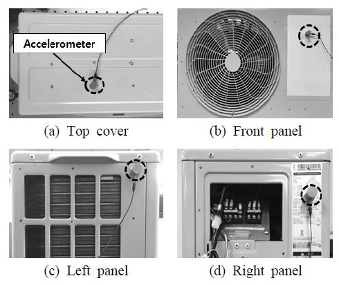
대상 실외기의 시험에서는 실외기의 팬 모터만 운전하였고, 회전수 범위는 500 rpm ~ 840 rpm에서 진동을 스캔하였다. 진동 측정 위치는 Fig. 1과 같이 상부 커버(top cover), 전면부 패널(front panel), 좌측 패널(left panel), 우측 패널(right panel)에서 관심주파수를 고려하여 5 Hz ~ 256 Hz에서 진동 스펙트럼을 측정하였다. 신호처리 과정에서 노이즈가 발생하기 때문에 0 Hz ~ 5 Hz 구간은 필터링하였다(7). 주파수 해상도(frequency resolution)는 0.125 Hz로 지정하였다. 측정장비는 LMS사의 FFT analyzer (SCM202)를 사용하였고 가속도 센서는 PCB사의 3축 가속도 센서(356A44)를 사용하였다. 실외기의 진동은 기계적 진동과 유동에 의한 진동이 있다. 기계적 진동은 모터의 전자기적 특성, 구조적 특성에 의해 발생되고, 유동에 의한 진동은 날개를 통과하는 공기의 상호작용에 의해 발생된다. 기계적 진동은 모터 회전수의 조화주파수(harmonic frequency)가 있으며, 유동에 의한 진동에는 날개 통과주파수(BPF; blade passing frequency)가 있다. 조화주파수(f)는 식 (1)과 같다.
| (1) |
실험결과는 Table 1에 높은 진동레벨을 가지는 회전수 범위와 패널에 대하여 정리하였다. 측정결과를 보면 600 r/min은 전면부 패널에서, 760 r/min에서는 좌, 우측 패널에서 1차 조화주파수의 진동레벨이 우세하게 나타났다. 상부 커버를 제외한 나머지 패널들에 대하여 1차 조화주파수가 지배적인 것을 확인할 수 있다.
2.2 ODS 분석
실외기의 운전 중 진동형상을 가시화하기 위하여 작동 중 변형 형상 분석을 실시하였다. 작동 중 변형 형상을 분석하기 위해서는 임의의 한 지점을 기준으로 하고 다른 지점들 간의 상호 스펙트럼(cross spectrum)을 측정하여야 한다. 각 위치의 진동신호를 측정하여 상호 스펙트럼으로 나타내면, 모든 위치별 진폭비와 위상차를 나타내는 전달률(transmissibility)을 계산할 수 있다. 작동 중 변형 형상 분석에서 전달률 H(f)은 기준점의 외부 잡음(extraneous noise)을 제거한 스펙트럼밀도함수로 표현되며 식 (2)와 같다.
| (2) |
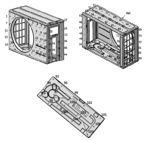
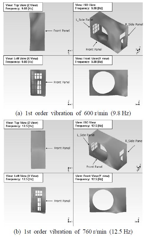
여기서 Gxx(f)는 기준점의 자기 스펙트럼밀도함수이고, Gxy(f)는 기준점과 측정지점의 상호 스펙트럼 밀도함수이다. 시험에서는 실외기의 상부 커버를 기준점으로 지정하고 Fig. 2와 같이 기준점을 포함하여 총 107지점의 상호스펙트럼을 측정하였다. Fig. 3은 진동레벨이 높게 발생한 회전수 600 r/min, 760 r/min의 작동 중 변형 현상을 나타내었다. 600 r/min에서 전면부 패널은 y방향(전후방향)으로, 하부는 z방향(상하방향)으로 진동하는 형상이다. 그리고 760 r/min에서는 실외기 전체가 x방향(좌우방향)으로 진동하는 형상과 하부가 z방향(상하방향)으로 진동하는 형상을 나타낸다. 따라서 1차 조화주파수로 인한 패널의 진동형상이 문제가 됨을 규명하고 실외기의 진동을 저감할 수 있는 개선안 도출이 필요하다.
3. 실외기의 진동해석
3.1 유한요소모델 및 경계조건
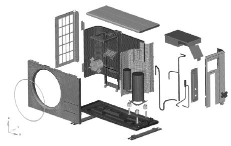
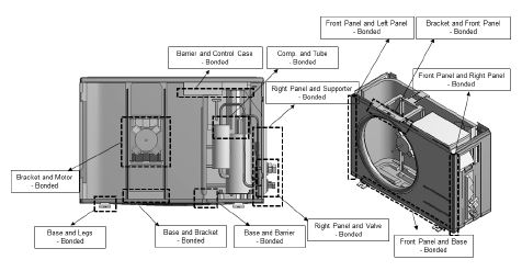
실외기는 3차원 설계 프로그램을 사용하여 두께가 얇은 판재부품과 얇은 구리 관 등은 셸(shell)요소로, 두께가 두꺼운 압축기와 모터 등은 솔리드(solid)요소로 모델링 하였다. 전체 유한요소모델은 Fig. 4에 나타내었다. 진동측정 시험조건과 동일하게 자유도의 구속조건을 부여하지 않았다. Fig. 5는 유한요소모델에 적용된 경계조건을 나타낸다. 실외기는 모든 부품들이 볼트로 연결되어 있기 때문에 접촉면의 절점을 공유하는 접착(bonded)조건을 부여하였다. 그리고 접촉영역의 표면을 효율적으로 연관시켜, 병진 및 회전 자유도가 고려되는 다중점 구속(MPC; multi point constraint)조건을 적용하였다. 해석에 사용한 물성치는 Table 2에 정리하였다.
3.2 진동모드 해석결과
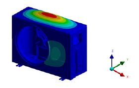
실외기의 유한요소모델은 범용 유한요소해석프로그램인 ANSYS V17.1(8)을 이용하여 진동모드 해석을 수행하고, 결과를 Table 3에 정리하였다. 자유도를 구속하지 않았기 때문에 6개의 강체모드(rigid body mode)가 0 Hz로 나타났다. 실외기의 내부 변형에너지를 가지는 변형모드는 1차 조화주파수 범위(8.25 Hz ~ 13.8 Hz)에서 존재하지 않고, 14 Hz(7차 모드)부터 존재하였다. 그리고 실외기의 패널이 가지는 변형모드는 12차부터 14차(31 Hz ~ 38.5 Hz)모드이므로 1차 조화주파수에 의한 공진이 아닌 것으로 판단된다. 상부 커버는 사용 회전수 범위 중 760 r/min에서 가장 높은 진동레벨이 발생했으며, 이는 날개 통과주파수(37.5 Hz)로 인해 상부 커버의 고유진동수와 일치함으로써 진동레벨이 높게 나타났다. 시험과 해석결과를 비교한 Table 4에서 약 2.7 %의 오차율로 유한요소모델을 이용한 모드해석의 결과가 신뢰성이 있음을 판단할 수 있다. 상부 커버의 모드형상은 Fig. 6에 나타내었다.
4. 실외기의 진동저감 대책
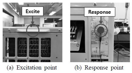
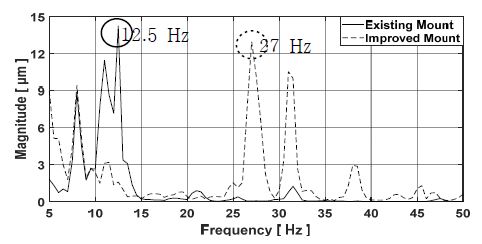
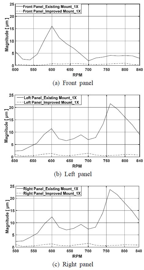
2.2절에서 분석한 결과로 실외기 전체가 좌우방향으로 움직이는 형상을 나타냈으며, 하부의 진동형상이 가장 컸기 때문에 마운트의 문제로 판단된다. 충격 응답 스펙트럼을 통해 마운트의 경도 개선안을 제시하고자 한다. Fig. 7에 가진점과 응답점의 위치를, Fig. 8에 측정결과를 나타내었다. 결과를 보면 실외기의 1차 운전주파수 범위(8 Hz ~ 13.8 Hz)인 12.5 Hz에서 진동레벨이 가장 우세하게 나타났다. 따라서 실외기의 공진주파수가 1차 회전주파수 범위를 회피하는 마운트 설계가 필요하다. 1차 회전주파수 범위 이하로 공진주파수를 이동시키는 방법은 경도가 더 낮은 고무를 사용해야 하지만, 실외기 부품 중 상대적으로 무거운 압축기로 인한 좌우측 무게차이로 고무의 경도는 제한적이다. 그러므로 기존의 경도 75.5 H(A)에서 10 H(A)높은 고무를 사용하였다. Fig. 8을 보면 공진주파수가 12.5 Hz에서 27 Hz로 1차 회전주파수 범위 이상으로 이동하였다. 실외기에 경도가 개선된 마운트를 적용하여 전과 후 측정결과를 총합진동레벨로 비교하였다. 가속도계로 측정한 진동레벨은 저주파 진동에 대해 낮은 신호를 생성하기 때문에 고주파 신호를 줄인 변위 값을 사용하였다. Table 5 ~ 7에 진동레벨을 정리하고 Fig. 9에 전면부, 좌, 우측 패널의 진동스펙트럼을 나타내었다. 결과를 보면 600 r/min에서 전면부 패널의 총합 진동레벨은 84 % 감소하고, 1차 성분의 진동레벨은 95 % 감소하였다. 760 r/min에서 좌측 패널의 총합 진동레벨은 80 % 감소하고, 1차 성분의 진동레벨은 97 % 감소하였다. 우측 패널의 총합 진동레벨은 80 % 감소하고, 1차 성분의 진동레벨은 97 % 감소하였다. 따라서 경도를 증가시킨 고무 마운트는 실외기 패널의 진동저감에 효과가 있음을 확인하였다.
5. 결 론
이 연구에서는 실외기 패널의 진동형상을 분석하고, 진동저감 대책을 수립하였다. 패널의 진동특성을 분석하기 위해 전체 회전수 범위에 대한 진동을 스캔하고, 진동레벨이 높게 존재하는 회전수 구간을 선정하여 작동 중 변형 형상을 분석하였다. 그리고 실외기의 전체 시스템에 대한 유한요소모델을 수립하고, 진동모드 해석을 통해 모드형상을 분석하였다. 충격 응답 스펙트럼을 통해 1차 회전주파수 범위에 존재하는 공진주파수를 도출하였다. 그리고 고무 마운트의 경도를 증가해 공진주파수를 1차 회전주파수 범위 이상으로 이동시켜 회피하였다. 그 결과 600 r/min에서 전면부 패널이 저감되었고, 760 r/min에서는 좌, 우측 패널의 진동이 저감되는 것을 확인하였다. 따라서 고무 마운트의 경도개선 방법은 실외기 패널의 진동저감에 효과가 있음을 검증하였다.
References
- Guedel, A., 2000, Noise of Propeller Fans Used in Air-Conditioning Units Reduction of a Household Refrigerator, Proceedings of the 29th International Congress on Inter-Noise and Noise-Con, Vol. 2000, No. 4, pp. 27∼30.
- Lee, S. B., Lee, J. H., Kim, H. J., Choi, J. K., Jin, S. H. and Park, Y. S., 1997, Flow Noise in the Outdoor Unit of an Air-conditioner, Proceedings of the KSNVE Annual Spring Conference, pp. 594∼601.
- Lee, S. B., Kim, K. H. and Joo, J. M., 2001, Design Parameter Analysis on the Performance and Noise of Axial Fan, Proceedings of the KSNVE Annual Autumn Conference, pp. 275∼281.
- Lee, S. B., Ahn, K. W., Baek, S. J., Kim, C. J. and Jeon, W. H., 2001, Noise prediction of Centrifugal Compressor Impeller based on Rapid Loading Calculation, Proceedings of the KSNVE Annual Autumn Conference, pp. 504∼511.
- Lee, B. C. and Kim, J. D., 2000, Experimental Analysis on the Resonator in the Rotary Compressor, Proceedings of the KSNVE Conference, pp. 1410∼1415.
-
Lee, B. C. and Kim, J. D., 2004, Experimental Analysis Using Taguchi Method on the Resonator in the Rotary Compressor for Air Conditioner, Transactions of the Korean Society for Noise and Vibration Engineering, Vol. 14, No. 1, pp. 3∼9.
[https://doi.org/10.5050/KSNVN.2004.14.1.003]

-
Suh, J. S., 2014, A Study on the Measurement of the Pipeline Displacement Vibration Using Accelerometers, Transactions of the Korean Society for Noise and Vibration Engineering, Vol. 24, No. 6, pp. 476∼482.
[https://doi.org/10.5050/KSNVE.2014.24.6.476]

- ANSYS User's Manual, Revision 17.1, 2016, ANSYS Inc.

Jong-Hui Baek received B.S. and M.S. degrees from Keimyung University in 2017, 2020. His research interests are the mechanical system design to reduce noise and vibration.

Won-Jin Kim received his Ph.D. from the Dept. of Mechanical Engineering at KAIST in 1993. He has been working for Dept. of Mechanical and Automotive Engineering as a professor since 1997. His research interest includes source and system identification, the mechanical system design to reduce noise and vibration.
