초음파센서용 압전 원판 변환기의 면내/면외 진동
© The Korean Society for Noise and Vibration Engineering
Abstract
This paper deals with the in-plane and out-of-plane vibrations of piezoelectric disc transducers, which are the main elements of ultrasonic sensors. In disc-type piezoelectric transducers, the fundamental mode is a radial mode, and the in-plane vibration of radial motion is coupled with the out-of-plane vibration of the axial motion. We developed an in-plane vibration theory, which was reported earlier, and theoretically analyzed the out-of-plane vibration and verified the theory by finite element analysis. We experimentally measured and compared the natural frequencies and verified the analysis results. In addition, we established a theoretical equation for the vibration distribution, which shows a bell-shape for the out-of-plane vibration in the thickness direction for the fundamental mode, as well as a theoretical equation of the natural frequency, which is inversely proportional to the radius.
Keywords:
Piezoelectric, Disc, Transducer, Vibration, Ultrasound, Sensor키워드:
압전, 원판, 변환기, 진동, 초음파, 센서1. 서 론
초음파 기술이 계측 제어용 센서 및 액추에이터 분야에 꾸준히 사용되고 있다(1). 특히 계측용 초음파센서는 유량이나 수위 측정 또는 차량 후방감지 등에 사용되어 왔다(2,3). 자동차 부품들이 전장화 되면서 초음파센서 활용이 주차보조 및 자율주행 등의 영역으로 확대되는 추세이다(4). 이들의 공통점은 거리측정이다.
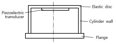
거리측정용 초음파센서의 주요 성능은 탐지거리 범위이다. 원거리 또는 중거리 측정에는 레이더 또는 라이더 센서가 사용되지만 수 미터 범위의 근거리 측정에는 초음파센서가 적합하다. 초음파센서의 최대 탐지거리를 확장하는 연구(5)와 최소 탐지거리를 단축하는 연구(6)가 병행되고 있다. 이러한 연구에서 가장 기본적인 부분은 초음파센서를 구성하는 요소들을 적절히 설계하는 것이다. 자동차에서 사용되는 초음파센서를 개략적으로 보이면 Fig. 1과 같다(7). 압전 변환기(piezoelectric transducer)가 전기 신호를 받아 진동하고 이에 따라 탄성판이 진동하여 초음파를 방사한다. 반사되어 되돌아오는 초음파를 감지하는 과정은 그 역순이다. 따라서 압전 변환기의 진동 특성 파악은 초음파센서 설계에 필수적이다.
초음파 변환기의 압전소자는 대개 원판형이다. 압전원판의 진동 특성에 대해서는 이미 많은 연구가 이루어졌다(8). 두께보다 지름이 훨씬 큰 압전원판의 기본모드는 반지름 치수에 의해 결정되는 반경모드이다(9). 원판형 압전 변환기의 면내 방사진동 특성을 다룬 연구에서, 반경모드의 반경방향 진동을 실험으로 입증한 바 있다(10). 초음파센서에서 탄성판을 가진하는 데에는 압전원판의 두께방향 진동이 기여하게 되므로, 반경모드의 두께방향 진동 특성 파악이 필요하다.
이 연구는 압전 원판 변환기의 반경모드에서 두께방향 진동인 면외 진동을 다루며, 그 특성에 영향을 주는 반경방향 진동인 면내 진동과 연계시킨다. 앞선 연구(10)에서 제시한 면내 진동의 이론을 발전시켜 면외 진동 분포를 이론적으로 해석하고, 이를 유한요소 해석으로 입증한다. 진동 특성 중 고유진동수에 대해서는 실험으로도 비교 검증한다.
2. 이론적 해석
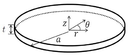
초음파센서의 주요 요소인 압전 원판 변환기의 개략도를 Fig. 2에 나타내었다. 두께가 t이고 반지름이 a이다. 윗면과 아랫면에 형성된 얇은 전극에 가해지는 전기신호에 따라 진동한다. 축대칭 운동을 다루면 원통좌표계 중에서 θ에 무관하여, 반경방향 운동 변위 u(r,z,t)와 두께방향 운동 변위 w(r,z,t)로써 운동을 묘사할 수 있으며, 이들을 변수분리 하여 표현하면 식 (1)과 같다.
| (1a) |
| (1b) |
여기서 A와 B는 진폭이다. 변형률은 다음과 같이 표현된다.
| (2a) |
| (2b) |
| (2c) |
원판이 자유로운 상태이므로 반경모드의 경계조건은 다음과 같이 r = a에서 원주면 응력으로 설정된다.
| (3) |
식 (3)을 만족하는 해를 구하여 다음과 같이 보고한 바 있다(10).
| (4) |
여기서 k는 파동수로서, k = qn/a (n = 1, 2, …)라고 표현할 때, PZT-4 재질의 경우에 근 qn = 2.07, 5.40, 8.58, …로부터 구할 수 있다(10). 진동수 f(=ω/2π)는 다음 식으로 계산된다.
| (5) |
여기서 c는 매질에서의 파동 전파속도로서, PZT-4에서 3460 m/s이다(10).
압전 원판에서 두께가 지름에 비해 작으므로 반경방향 변위 u(r,z,t)의 두께방향 분포 Z(z)가 거의 균일한 것으로 가정하여 다음과 같이 표현한다.
| (6) |
두께방향으로 분극된 압전 원판 변환기에서, 원판 양면의 전극에 교류 전압이 인가되면 두께방향 진동이 발생한다. 두께방향 변형이 푸아송 비 효과에 따라 반경방향을 야기한다. 부록의 식 (A3)로부터 다음과 같이 표현된다.
| (7) |
| (8) |
이로부터 다음 관계가 나타난다.
| (9a) |
| (9b) |
식 (9a)를 적분하면 다음과 같다.
| (10) |
식 (4)의 도함수가 다음과 같으므로
| (11) |
두께방향 변위의 반경방향 분포 R(r)이 식 (9b)에 의해 다음과 같이 표현된다.
| (12) |
반경방향 좌표 r을 반지름 a로 나누어 정규화 한 반경 좌표 과 반경방향 최대 변위 Umax로 나누어 정규화 한 반경방향 면내 진동 변위 의 관계는 다음과 같다.
| (13) |
같은 방식으로 두께방향 최대 변위 Rmax로 나누어 정규화 한 두께방향 면외 진동 변위 는 다음과 같다.
| (14) |
식 (5)에서 계산되는 고유진동수와 식 (13) 및 (14)로부터 계산되는 진동형상을 다른 방법으로 구한 결과들과 제5절에서 비교한다.
3. 유한요소 해석
이론적 해석 결과를 검증하기 위하여 유한요소 해석을 하였고, 상용 소프트웨어인 ANSYS를 사용하였다.
3.1 해석 모델
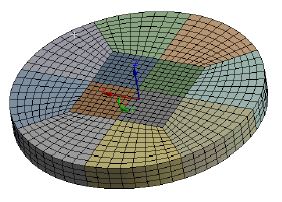
Fig. 2에 보인 압전 원판을 대상으로 유한요소 모델을 형성한 예를 Fig. 3에 제시하였다. 반지름이 5 mm이고 두께가 1 mm인 경우로서, SOLID185 요소 3332개로 구성되었다. 재질은 PTZ-4로서, 탄성계수 및 압전상수 등의 물성치는 참고문헌 (10)에서 인용하여 부록의 Table A에 제시하였다. 원판 양면의 전극은 두께가 무시되고, 전극에 교류전압이 인가되는 것으로 경계조건이 설정된다.
3.2 해석 결과
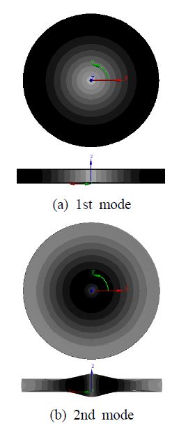
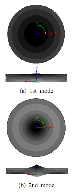
해석 결과 중에서 면내 진동 분포를 Fig. 4에 나타내었다. (a)와 (b)의 위 그림은 축대칭 반경방향 분포를 보여주고, 아래 그림은 단면도로서 반경방향 분포와 두께방향 분포를 보여준다. 같은 방식으로 면외 진동변위 분포를 Fig. 5에 나타내었다.
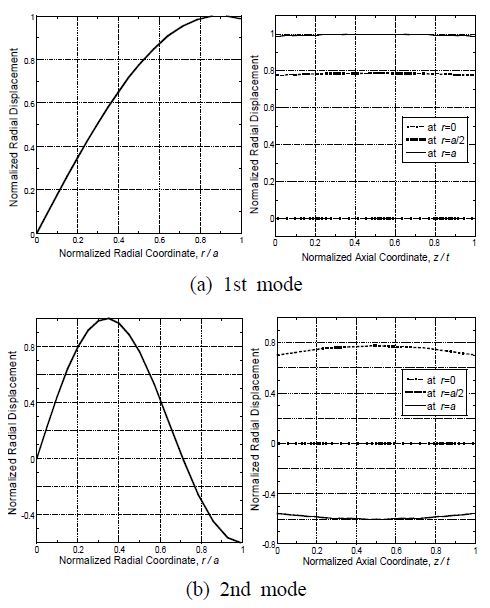
Fig. 4에 제시된 면내 진동 결과로부터 데이터를 추출해서 최대진폭으로 정규화 하여 그래프로 나타낸 것이 Fig. 6이다. 이론적으로 유도된 식 (6)에서는 면내 진동이 두께방향으로 균일하다고 표현되었지만, 유한요소 해석 결과인 Fig. 6의 오른쪽 그래프에서는 완전히 균일하지는 않은 것으로 나타났다.
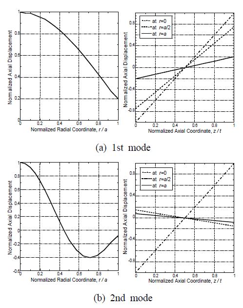
또한 Fig. 5의 면외 진동 결과로부터 정규화 하여 나타낸 그래프가 Fig. 7이다. 이론적으로 유도된 식 (10)에서 면외 진동 분포가 두께방향으로 1차함수 형태라고 예상되었고, Fig. 7의 오른쪽 그래프에서도 그와 같은 경향을 보인다.
4. 실 험
이론적 해석과 유한요소 해석으로 구한 고유진동수를 비교 검증하기 위한 실험을 하였다.
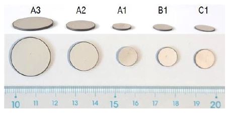
실험에 사용된 압전 원판은 ㈜동일기연 제품으로서, 재질은 PTZ-4이다. 지름 3가지와 두께 3가지로 하여 Table 1에 기재한 바와 같이 5종의 시편을 선정하였다. 이들의 사진을 Fig. 8에 제시하였다.
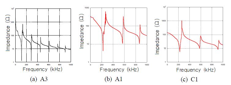
압전소자의 고유진동수는 주파수에 따른 임피던스를 측정하여 임피던스 곡선의 극소값에 해당하는 주파수로써 파악할 수 있다. 이 연구에서는 Agilent 4192A impedance gain/phase analyzer를 사용하였다. 측정된 임피던스 곡선의 예를 Fig. 9에 나타내었다. 각 시편 종류별로 3개씩의 시편에 대해서 실험을 반복하여 고유진동수 평균값을 구하였다.
이 연구에서 진동분포를 측정하는 실험은 하지 않았다. 앞선 연구(10)에서는 지름이 25 mm 이상의 시편을 대상으로 in-plane laser interferometry에 의해 면내 진동을 측정한 바 있다. 이 연구의 대상 시편은 지름이 작아서 그 방법에 적합하지 않았다.
5. 결과 비교 및 고찰
진동분포에 대해서 이론적 해석과 유한요소 해석의 결과를 비교하고, 고유진동수에 대해서 3가지 결과를 비교하며 치수에 따른 경향을 고찰한다.
5.1 진동 분포
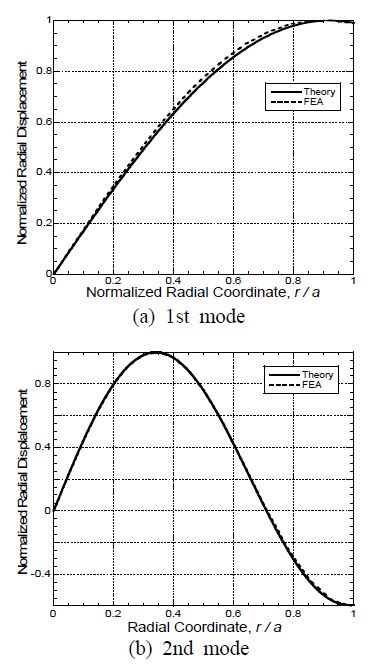
이론적 분포 계산 식 (13)으로부터 1차모드(n = 1)와 2차모드(n = 2)의 반경방향 면내 진동의 분포를 계산하여 Fig. 10에 실선으로 나타내었다. 유한요소 해석으로 구하여 Fig. 6의 왼쪽에 제시한 결과를 Fig. 10에 점선으로 나타내었다. 비교해서 알 수 있다시피, 면내 진동 분포의 이론적 해석 결과와 유한요소 해석 결과가 서로 유사하다.
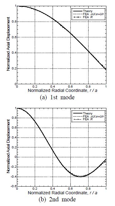
식 (14)로부터 1차모드와 2차모드의 두께방향 면외 진동의 분포를 계산하여 Fig. 11에 실선으로 나타내었다. 한편, 식 (9b)에 따라 Fig. 6의 왼쪽 그래프들로부터 (∆U/∆r)+(U/r)를 추출하여 Fig. 11에 점선으로 나타냈고, Fig. 7의 왼쪽에 제시한 결과를 Fig. 11에 1점 쇄선으로 나타내었다. 이 그래프들을 비교하여, 이론적으로 계산한 결과와 유한요소 해석에서 산출한 두 가지 결과가 유사한 것이 확인되었다.
이 연구에서 목적한 대로 압전 원판 변환기의 면내 진동과 면외 진동이 연계됨을 입증하였다. 기본모드의 면외 진동 분포 형상이 축대칭 종모양인 것도 확인하였다. 이는 압전 원판 변환기가 포함된 초음파 센서의 진동분포를 유한요소 해석으로 구한 결과와 일관성이 있다(11).
5.2 고유진동수
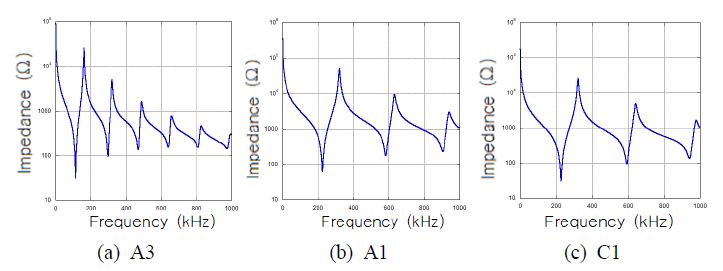
Table 1에 제시한 시편에 대해 3가지 방법으로 고유진동수를 구하여 Table 2에 기재하였다. 유한요소 해석 과정에서 고유진동수를 파악하기 위해 먼저 구한 임피던스 곡선을 Fig. 12에 나타내었다. 3가지 방법으로 구한 고유진동수가 매우 유사하다. 3가지 결과에서 1차 고유진동수는 거의 일치하였으나 2차 고유진동수는 이론적 결과가 5 % 정도 어긋났다. 이론적 해석에서 반경모드에 두께방향 운동이 없다고 전제하였는데, 1차 모드에서는 타당하지만 2차모드에서는 그렇지 않기 때문인 것으로 판단된다.

Comparison of natural frequencies obtained by theoretical calculation, finite element analysis, and experiment
고유진동수는 압전원판의 두께에 상관없지만 지름에 따라 다르다. 이는 원주면 경계조건에 영향 받는 반경모드이기 때문이다. 반지름에 따른 고유진동수를 Fig. 13에 나타내었다. 고유진동수가 반지름에 반비례한다. 1차 고유진동수와 지름의 곱은 2.28 kHzㆍm임을 확인하였다. 재질이 PZT-4인 압전 원판의 1차 고유진동수는 이 수치를 지름으로 나누어 실용적으로 추정할 수 있다.
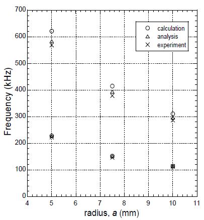
Comparison of natural frequencies obtained by theoretical calculation, finite element analysis, and experiment
Table 2에서 시편 A1, B1, C1의 결과에서 확인되다시피, 두께 대비 지름이 10 이상인 압전원판에서 저차의 반경모드 고유진동수는 두께에 상관없다. 한편, 시편 A1, A2, A3의 결과에서 확인되듯이, 저차의 반경모드 고유진동수는 반지름에 따라 다르다. 이는 원주면 경계조건에 영향받기 때문이다.
6. 결 론
초음파센서의 핵심 요소인 압전 원판 변환기의 면내 진동과 면외 진동의 연계성을 다루었다. 원판형 압전 변환기에 대한 이론적 해석으로 반경방향 운동인 면내 진동으로부터 두께방향 운동인 면외 진동을 표현하였다. 유한요소 해석으로 진동분포를 구하여 이론적 해석 결과를 비교 검증하였다. 임피던스 측정 실험으로 고유진동수를 구하여 이론적 계산 및 유한요소 해석 결과를 비교 검증하였다.
면내진동 분포에 대해서 이론적 해석과 유한요소 해석 결과가 유사하였다. 면외진동 분포에 대해서도 두 가지 결과가 유사하였다. 면외진동 분포가 축대칭 종모양 분포인 것을 식으로 표현할 수 있게 되었다.
고유진동수는 3가지 방법으로 얻은 결과가 일치하였다. 원판형 압전 변환기의 기본모드 고유진동수는 두께 대비 지름이 10 이상인 경우에 두께에 상관없지만 지름에 반비례한다. 재질이 PZT-4인 압전원판의 1차 고유진동수와 지름의 곱은 2.28 kHzㆍm임을 파악하였고, 이로부터 실용적으로 고유진동수를 추정할 수 있다.
Acknowledgments
이 성과는 정부(과학기술정보통신부)의 재원으로 한국연구재단의 지원을 받아 수행된 연구임 (No. NRF-2020R1F1A1048453).
References
-
Busch-Vishniac, I. J., 1999, Electromechanical Sensors and Actuators, Springer, New York, Ch. 5.
[https://doi.org/10.1007/978-1-4612-1434-2]

- Lynnworth, L. C., 1989, Ultrasonic Measurements for Process Control, Academic Press, Boston.
- Kim, J. O., 2000, Sensors and Actuators Using Ultrasound, Journal of the KSNVE, Vol. 10, No. 5. pp. 723~728.
-
Xu, W., Yan, C., Jia, W., Ji, X. and Liu, J., 2018, Analyzing and Enhancing the Security of Ultrasonic Sensors for Autonomous Vehicles, IEEE Internet of Things Journal, Vol. 5, No. 6, pp. 5015~5029.
[https://doi.org/10.1109/JIOT.2018.2867917]

-
Lim, S. G. and Kim, J. O., 2018, Acoustic Directivity of an Ultrasonic Sensors Depending on Horn Guide Shape, Transactions of the Korean Society for Noise and Vibration Engineering, Vol. 28, No. 6, pp. 707~712.
[https://doi.org/10.5050/KSNVE.2018.28.6.707]

-
Lim, S. G., An, J. H. and Kim, J. O., 2020, Shortening the Minimum Detectable Distance in an Ultrasonic Sensor for Automobiles by a Waveguide, Transactions of the Korean Society for Noise and Vibration Engineering, Vol. 30, No. 4, pp. 396~405.
[https://doi.org/10.5050/KSNVE.2020.30.4.396]

- Yoo, G. S., Lee, T. H. and Chae, M. K., 2017, Ultrasonic Transducer for Vehicle, Korea Patent 10-1,728,225.
-
Ho, S.-T., 2007, Modeling of a Disk-type Piezoelectric Transformer, IEEE Transactions on Ultrasonics, Ferroelectrics, and Frequency Control, Vol. 54, No. 10, pp. 2110~2119.
[https://doi.org/10.1109/TUFFC.2007.506]

-
Meitzler, A. H., O’Bryan, Jr., H. M. and Tiersten, H. F., 1973, Definition and Measurement of Radial Mode Coupling Factors in Piezoelectric Ceramic Materials with Large Variations in Poisson’s Ratio, IEEE Transactions on Sonics and Ultrasonics, Vol. 20, No. 3, pp. 233~239.
[https://doi.org/10.1109/T-SU.1973.29750]

-
Kim, D. J., Oh, S. H. and Kim, J. O., 2015, Measurements of Radial In-plane Vibration Characteristics of Piezoelectric Disk Transducers, Transactions of the Korean Society for Noise and Vibration Engineering, Vol. 25, No. 1, pp. 13~23.
[https://doi.org/10.5050/KSNVE.2015.25.1.013]

-
Seon, S. O., Kim, J. O., Chae, M. K. and Yoo, G. S., 2018, Acoustic Characteristics Depending on the Vibration Distribution of Ultrasonic Sensors, Transactions of the Korean Society for Noise and Vibration Engineering, Vol. 28, No. 4, pp. 490~500.
[https://doi.org/10.5050/KSNVE.2018.28.4.490]

Appendix
부 록
등방성 탄성원판에서 응력과 변형률의 관계는 Hooke의 법칙에 plane stress 조건인 σ2 = 0를 적용하여 다음과 같다.
| (A1a) |
| (A1b) |
| (A1c) |
여기서 E 와 ν는 각각 영률과 푸아송 비이다. 식 (A1a)와 (A1b)의 합은 다음과 같다.
| (A2) |
식 (A2)와 식 (A1c)로부터 다음과 같은 변형률 관계식을 얻는다.
| (A3) |
이 결과는 등방성 탄성체에 적용되는 식이다. 압전체는 이방성이지만 PZT-4와 같이 입방 대칭성(cubic symmetry)이면서 등방성에 가까운 재질에서는 약간의 오차를 감수하고 적용될 수 있다.

Byung Ju Baek received the B.S. degree in Mechanical Engineering from Soongsil University in 2021. During his stay at Soongsil as an undergraduate student, he was working on vibration characteristics of piezoelectric discs for ultrasonic sensors.

In Jae Heo received the B.S. degree in Automation Engineering from Dongyang Mirae University in 2020. He is currently a master candidate as a graduate student at Soongsil University. He is working on ultrasonic sensors and waves.

Jin Oh Kim received the B.S. and M.S. degrees in mechanical engineering from Seoul National University in 1981 and 1983, respectively, and the Ph.D. degree from University of Pennsylvania in 1989. For ten years he has got research experiences at Korea Research Institute of Standards and Science, Northwestern University, and Samsung Advanced Institute of Technology. Since 1997, he has been working at Soongsil University, where he is currently a Professor of mechanical engineering. His research interests are in the area of ultrasonic sensors and actuators using mechanical vibrations and waves.
