Micro Hexapod Robot Using Dual-axis Electromagnetic Actuator
© The Korean Society for Noise and Vibration Engineering
Abstract
Microrobots utilized in industrial applications or medical tasks have been researched by applying various types of actuators. However, compared with live organisms, the majority of compact actuators are not able to sufficiently supply the power demanded for robotic implementations. This paper presents a novel design for a hexapod microrobot that uses electromagnetic oscillatory actuators. Each two-degree-of-freedom (2-DOF) leg moves by utilizing compact dual-axis electromagnetic actuators. First, the structure and kinematics of the hexapod microrobot are presented and theoretically analyzed. In our study, a tripod gait is utilized to enable the robot to walk on the desired terrain. All virtual models and physical prototypes are detailed to test the motion plan of the proposed system. Finally, simulation and experimental results are used to evaluate the performance and verify the ability of the novel design of our hexapod microrobot.
초록
최근 소형 이동로봇에 대해 의료용 및 산업용으로 많은 연구가 이루어지고 있다. 많은 연구자들이 다양한 구동기를 활용하여 소형 이동로봇을 개발하고 있다. 그러나 대부분의 소형 크기의 구동기들은 생체시스템에 비해 충분한 성능을 갖고 있지 않다. 이 연구에서는 전자기 진자형 구동기를 사용하여 소형 6족 이동로봇의 새로운 디자인을 제시한다. 6개의 다리 운직임은 소형 2축 전자기 구동기로 구성되어 움직인다. 먼저 소형 6족 로봇에 대한 구조와 기구학이 소개되고 이론적으로 분석된다. 이 연구에서는 3점 지지 걸음 방법이 적용되어 평면에서 걷기가 가능함을 보인다. 가상 모델 로봇과 실제 제작된 로봇이 자세히 설명되고 각 모션 플래닝을 수해하였다. 마지막으로 시뮬레이션 결과와 실험 결과를 보이고 제안된 소형 6족로봇의 성능을 비교 검증하였다.
Keywords:
Hexapod Robot, Electromagnetic Actuator, Tripod Gait, Micro Robot, Simscape키워드:
6족 로봇, 전자기구동기, 3점 지지, 마이크로 로봇, 심스케이프1. Introduction
Recently, the studies on diminished robots or micro robots in the field of inspection, rescue, industrial or medical applications have been augmented significantly. Common moving systems such as wheeled driving and crawler are not suitable for these kinds of robot. Contact force alteration, disproportionate actuation and maneuvering friction called “stick-slip”, “impact drive” and “inchworm like motion”(1) are proposed as novel moving mechanical systems recently.
Moreover, lead zirconate titanate (PZT)(2) shape memory Alloy (SMA)(3), electroactive polymers etc. considered as moving mechanism are also implemented to develop on novel actuators of micro robots.
Nevertheless, they are inefficient to accommodate enough demanded power for robot tasks due to the compact size which the acting force reduces intensely as following size diminution(4). Consequently, comparing with live organisms, the majority of compact actuators are insufficient to supply enough demanded power for robotic implementations.
On the contrary, electromagnetic actuators have a lot of advantages such as rapid response, low driving voltage, large displacements, low internal damping, sufficient power, uncomplicated control law and low price(5,6). Electromagnetic actuators are widely used for insect-inspired flapping-wing Robot(7), micro crawling robot(8~10), 4-DOFs modular serial manipulator(11). Nonetheless, hexapod robots utilized electromagnetic actuators are seldom studied. Hence, in this paper we propose a novel design of micro hexapod robot using dual–axis electromagnetic actuator (DEA) with a simple structure. At first, the concept of a DEA is theoretically analyzed in chapter 2. Then, we propose physical prototype and forward kinematic of the hexapod robot applied DEA to conduct the tripod gait in the chapter 3. In final chapter, the virtual model of the hexapod robot is given and evaluate the dynamic performance of the system via simulation and experimental results.
2. Micro Hexapod Robot Using Dual-axis Electromagnetic Actuator
2.1 Design and Working Principle of Dual-axis Electromagnetic Actuator
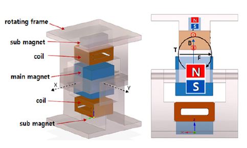
The design of dual-axis electromagnetic actuators (DEA) are relied on the structure of electromagnetic oscillatory actuators (EOA) which vacillate between desired bound. Following the Fig. 1, a DEA comprises double perpendicular frames (one fixed frame and one rotated frame) which are aligned together via another free-moving frame(5). This free-moving frame is appended on two axes so that it is able to revolve around these axes. Besides, each coil which are mounted to fixed frame or rotated frame has 820 turns with a resistance of 58 Ω. The max power to supply the coil can reach 6 V maximum. These dual energized coils will move a permanent magnet which is inserted inside the free-moving frame. Moreover, each side of the DEA comprises a built-in permanent magnet that place in contrary direction to the magnet of free-moving frame to converge and retain the magnetic field in the linear tendency as shown in Fig. 1. The Neodymium (ND35) is utilized for all permanent magnets due to the most powerful commercialized product. In addition, all frames are designed and conducted with ABS material to reduce the heat tolerances during printing process. The working principle of the proposed DEA is based on engendering Lorentz force among the permanent magnets and energized coils. This force is altered the direction by varying the current direction flown inside the coils and defined following left-hand rule. Consequently, free-moving frame is able to revolve around x-axis when supplying the current to the upper coil. In the same way, the energized coil of the rotated frame creates a torque in order to rotate its frame around the y-axis.
2.2 Micro Hexapod Robot Using Dual-axis Electromagnetic Actuator
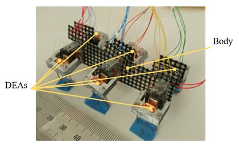
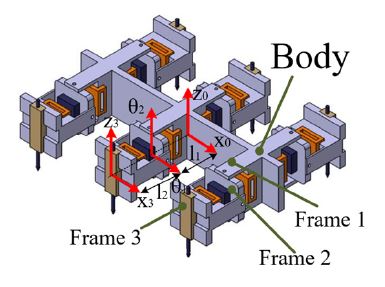
In this study, we design the hexapod with 2-DOF leg is based on the structure of the DEA. The robot consisted of six DEA modules aligned to the main body of the robot that illustrated in the Fig. 2.
Each three parallel actuated modules are arranged symmetrically at both side of the body. The robot has 22 mm height, 52 mm width, 71 mm length and 22 g weight. The gaps between two narrow legs are 63 mm and 111 mm of each side and two symmetric sides, respectively. At the end of each rotated frame, a double rods are mounted to the end of rotated frame to lift the body from the ground. A rubber pad is fixed at the bottom of the double rods to maintain the stability and friction force between the leg and ground.
3. Kinematic and Gait Design of Micro Hexapod Robot
3.1 Kinematic
The forward kinematic model of the hexapod robot is determined using Denavit-Hartenberg (DH) rule. Four reference systems maintain path from the body frame to the foot, with last three of them relative the leg, as shown in Fig. 3.
We call is the j-th leg foot-tip position in the global reference system and is the j-th foot-tip position in the foot coordinate system (second following reference system). The relation between the foot coordinate frame and the body frame can be obtained as follows:
| (1) |
Where, refers to the transformation matrix between the body coordinate frame and the global coordinate frame, refers to the transformation matrix between the j-th leg coordinate frame and body coordinate frame, and are the transformation matrix between the neighboring coordinates frames of the j-th leg and are given as:
| (2) |
Where, Cθijand Sθijdenote cosθij and sinθij, respectively; αij, aij, dij and θij are the Denavit-hartenberg parameters with the specific values provided in the Table 1.
3.2 Gait Design
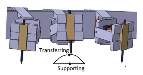
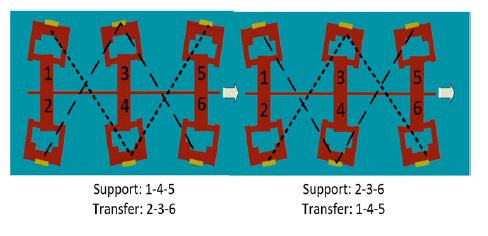
Following the path planning shown in Fig. 4, the motion of the robot is operated by six legs which conduct in a sequence to lift and move the body forward that called supporting stage and transferring stage, respectively.
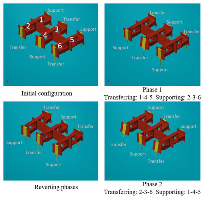
In our study, the tripod gait is implemented to the robot so leg groups are defined like as 1-4-5 and 2-3-6. Firstly, group 1-4-5 supports to hold and move body forward while group 2-3-6 steps up to transfer the next transition phase. Then, the subsequent phase is conducted by converting the stage of each group from the preceding phase. The motion of both phases are presented in Fig. 5. Finally, the robot maintains reverting stages of each group in a sequence to move the robot forward continuously.
4. Gait Simulation and Experiment of Micro Hexapod Robot
4.1 Simulation of Micro Hexapod Robot
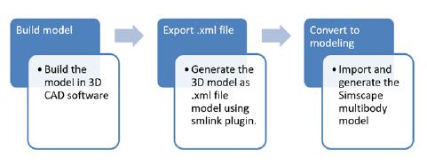
In this study, the tripod gait of micro hexapod robot is simulated to verify the walking ability of the proposed prototype. Firstly, a 3D CAD model of the robot is designed with actual parameters by utilizing CAD software. Then, the model is converted to xml-type model for importing to the Simscape Multibody physics engine from Matlab/Simulink. In detail, the process for converting a 3D CAD model to Simscape Multibody model is described in Fig. 6.
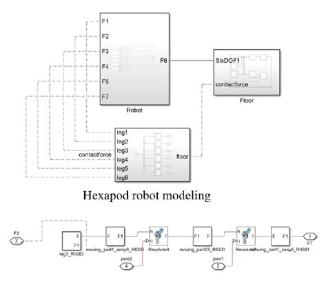
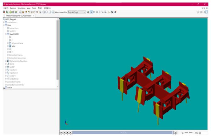
The result of the modeling for MHR consisted of three subsystems is described in Fig. 7. The Robot subsystem is the modeling of the MHR includes of the masses, inertial moments, physical dimension of body and legs. We also design the Floor subsystem and Contact-force subsystem to model the interaction among the legs and ground. Besides, a 3D mechanics explorer shown in Fig. 8 is enable to observe the motion of the robot intuitively.
4.2 Simulation Result
The gait simulation is implemented in this study to verify the motion planning of two stages: transferring and supporting for all legs the MHR presented in the previous chapter. The result of the tripod gait implemented by reverting the stages of each phase is shown in Fig. 9 It indicates that the MHR successfully generates the straight walking when applying the desired paths.
4.3 Experimental Result
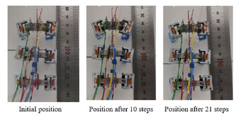
In this paper, we also implement the tripod gait test for the physical prototype of the MHR. Following the experimental result presented in Fig. 10, the MHR completed 21 steps for 20 seconds with 15 mm displacement. Thus, the robot reaches 0.75 mm/s in speed and the conduct a distance of 0.71 mm each step. The results validate the performance of the proposed MHR using DEAs when conducting the tripod gait on the flat ground.
5. Conclusion
This study proposed a novel design of a micro hexapod robot using dual-axis electromagnetic actuators. Both virtual prototype and physical prototype are presented to implement the tripod gait for verify the performance of the robot in simulation and experiment. The results indicates the robot is able to reach 0.75 mm/s in speed and the conduct a distance of 0.71 mm each step.
기 호 설 명
| : | j-th leg foot-tip position in the global reference system |
| : | j-th foot-tip position in the foot coordinate system |
| : | Transformation matrix between the body coordinate frame and the global coordinate frame |
| : | Transformation matrix between the j-th leg coordinate frame and body coordinate frame |
| : | Transformation matrix between the neighboring coordinates frames of the j-th leg |
| : | Denote cosθij and sinθij, αij, aij, dij and θij: the Denavit-Hartenberg parameters |
Acknowledgments
This research was supported by the research fund of Hanbat National University in 2020.
References
-
Shin, B. H. and Lee, S., 2012, Micro Mobile Robots Using Electromagnetic Oscillatory Actuator, 4th IEEE RAS & EMBS International Conference on Biomedical Robotics and Biomechatronics (BioRob), pp. 575~580
[https://doi.org/10.1109/BioRob.2012.6290681]

-
Hoffman, K. L. and Wood, R. J., 2011, Myriapod-like Ambulation of a Segmented Microrobot, Auton Robot, Vol. 31, p. 103
[https://doi.org/10.1007/s10514-011-9233-4]

-
Mansour, N. A., Jang, T., Baek, H., Shin, B., Ryu, B. and Kim, Y., 2020, Compliant Closed-chain Rolling Robot Using Modular Unidirectional SMA Actuators, Sensors and Actuators A: Physical, Vol. 310
[https://doi.org/10.1016/j.sna.2020.112024]

- Shim, H., 2018, Design of 6-legged Mobile Robot using 2-DOF Electro-magnetic Actuator, Master’s Thesis, Hanbat National University, Daejeon.
-
Kim, Y. S., Shim, H. H., Lee, K. M. and Shin, B. H., 2017, Development of Miniaturized 2-DOF Electromagnetic Actuator Module, Journal of the Control Robot System Society, Vol. 23, No. 7, pp. 546~551
[https://doi.org/10.5302/J.ICROS.2017.17.0008]

-
Kim, K. H., Oh, D. H., Shin, B. H. and Lee, S. Y., 2009, A HDD Latch Design Using Electro-magnetic Force of VCM Actuators, Transactions of the Korean Society for Noise and Vibration Engineering, Vol. 19, No. 8, pp. 788~794.
[https://doi.org/10.5050/KSNVN.2009.19.8.788]

-
Zou, Y., Zhang, W. and Zhang, Z., 2016, Liftoff of an Electromagnetically Driven Insect-inspired Flapping-wing Robot, IEEE Transactions on Robotics, Vol. 32, No. 5, pp. 1285~1289
[https://doi.org/10.1109/TRO.2016.2593449]

-
Lee, Km., Kim, Y., Paik, J. K. et al., 2015, Clawed Miniature Inchworm Robot Driven by Electromagnetic Oscillatory Actuator, Journal of Bionic Engineering, Vol. 12, No. 4, pp. 519~526
[https://doi.org/10.1016/S1672-6529(14)60142-6]

-
Shin, B., Kim, Y., Paik, J. et al., 2018, Miniaturized Twin-legged Robot with an Electromagnetic Oscillatory Actuator, Journal of Bionic Engineering, Vol. 15, pp. 106~113.
[https://doi.org/10.1007/s42235-017-0008-2]

-
Liu, X., Liu, Z., Qi, M. et al., 2019, A Fast-moving Micro Crawling Robot with Direct Electromagnetic Driving Mechanism, IEEE 32nd International Conference on Micro Electro Mechanical Systems (MEMS), pp. 6~9
[https://doi.org/10.1109/MEMSYS.2019.8870694]

-
Mansour, N. A., Shin, B., Ryu, B. and Kim, Y., 2021, Development of a Novel Miniaturized Electromagnetic Actuator for a Modular Serial Manipulator, Actuators, Vol. 10, No. 14
[https://doi.org/10.3390/act10010014]


Quang Hoan Le received a B.S. in Mechatronics Engineering from Hochiminh University of Technology in 2010. He received a Ph.D. in school of Mechanical Engineering from University of Ulsan in 2015. He was a lecturer at Hochiminh University of Technology from 2018 to 2020. Currently, he is working at Hanbat National University as a Postdoctoral researcher of mechanical engineering. His research interests are in the area of field robot, legged robot, motion control and electromagnetic actuator.

WangHun Lee received a B.S. in Mechanical Engineering from Hanbat National University in 2019. Since 2016, he has been working at Applied robotics and mechanics Lab of Hanbat National University, where he is currently studying M.S. of mechanical engineering. His research interests are in the area of bio-inspired robot, legged robot.

YoungShik Kim received a M.S. and Ph.D. in Mechanical Engineering from University of Utah in 2003 and 2008. Since 2011, he has been working at Hanbat National University, where he is currently a Professor of mechanical engineering. His research interests are in the area of smart actuator, motion control, bio-inspired robot, sensor fusion.

Bong-Jo Ryu received a M.S. and Ph.D. in Mechanical Engineering from Yensei University in 1983 and 1988. Since 1989, he has been working at Hanbat National University, where he is currently a Professor of mechanical engineering. His research interests are in the area of structure vibration, control, bar elastic safety.

Buhyun Shin received a B.S. and Ph.D. in school of Mechanical and aerospace Engineering from Seoul National University in 2001 and 2007. Since 2012, he has been working at Hanbat National University, where he is currently a Professor of mechanical engineering. His research interests are in the area of electromagnetic actuator, smart actuator, bio-inspired robot.
