저주기 피로를 고려한 3ply 벨로즈형 신축관이음의 내진성능 실험
© The Korean Society for Noise and Vibration Engineering
Abstract
Pipes can be damaged by strong external forces such as earthquakes. In particular, gas leaks and interruptions to water supply can cause serious secondary damage. This is one of the damage factors caused by earthquakes in urban areas. Bellows-type expansion joints for pipes are flexible and have low rigidity and good adaptability to relatively large deformations. Therefore, bellows-type expansion joints can be applied as seismic separation joints to improve the seismic performance of pipes. In this study, seismic performance considering low cycle fatigue was estimated for bellows-type expansion joints. Monotonic and cyclic loading tests for bending were performed on 80A 3ply bellows-type expansion joints manufactured by laminating three layers of 0.3 mm stainless steel plates. In the cyclic loading test, the multi-step increasing amplitude cyclic loading test to which the displacement history is amplified stepwise was applied and a constant-amplitude cyclic loading test considering various amplitudes was used to estimate the low-cycle fatigue life. In the case of the constant-amplitude cyclic loading tests, low cycle fatigue behavior was observed for 1/4 amplitudes of leakage displacements of monotonic loading tests.
Keywords:
Seismic Performance, Expansion Joint, Bellows, Low Cycle Fatigue키워드:
내진성능, 신축관이음, 벨로즈, 저주기 피로1. 서 론
전 세계적으로 자연재해의 발생빈도는 증가하는 추세이다. 인구의 도시 집중화, 시설설비의 대형화에 따라 예상되는 지진피해의 규모는 증가하고 있으나 지진예측의 불확실성으로 내진설계의 필요성이 강조되고 있다. 지진과 같은 강한 외력은 시설의 기능상실을 동반하는 손상을 유발할 수 있다. 특히 라이프라인인 배관의 경우, 손상에 의한 가스누출과 소방용수의 공급중단 등으로 가스폭발, 화재 등의 심각한 2차 피해를 초래할 수 있다. 이는 도시지역에서 지진으로 인한 피해요인 중 하나이다.
배관은 외기에 노출되는 환경에 설치되는 배관과 지하에 매설하는 배관으로 구분할 수 있다. 구조물 내·외부에 설치되는 배관은 지진에 의한 관성력 또는 두 지지점 사이의 위상차에 의해 작용하는 반복하중과 허용한계를 초과하는 상대변위에 의한 손상이 대표적이다. FEMA E 74(1)에서는 비구조요소의 지진 피해 유형을 관성력에 의한 전도 및 미끄러짐, 구조물의 층과 층 사이의 상대변위와 독립된 두 구조물 사이의 상대변위로 구분하고 있다. ASCE 7(2)에서는 배관과 같은 연성 부품은 지진으로 인한 지지점 사이의 상대변위가 관성력보다 더 중요할 수 있음을 제시하고 있다. 수계소화설비 배관의 경우 과도한 지진변위에 의한 손상을 방지하기 위하여 지진분리이음의 적용이 요구되기도 한다(3,4). 또한 배관의 지진에 의한 주요 손상모드는 큰 변위와 동적인 반복하중에 의한 저주기 피로(low cycle fatigue)임이 많은 연구를 통해 증명되었다(5~8). 따라서 배관의 내진성능평가를 목적으로 지진취약부인 피팅과 관이음부의 지진거동을 관찰하고 한계성능을 평가하기 위한 연구가 수행되었다. 그루브 조인트 및 압착식 조인트와 같은 무용접 관이음이 지진분리이음으로 적용된 수계소화설비 배관을 대상으로 내진설계기준의 최대허용층간변위를 고려한 층간변형모사 반복하중재하실험이 수행되었다(9,10). 내진성능평가방법의 제시를 위하여 배관시스템의 실험결과와 주요 요소실험의 결과가 비교분석 되었으며 유한요소 해석으로 배관의 지진거동을 분석하고 내진성능을 평가하기 위한 연구 또한 수행되고 있다(11,12).
매설된 배관은 석유, 가스, 물 등을 운송하는 주요 라이프라인으로써 일반적으로 지리적으로 먼 거리를 연결하기 위해 사용된다. 이러한 매설배관은 지진으로 인해 발생할 수 있는 단층, 액상화, 지반침하, 산사태 등의 영구지반변형에 의한 과도변위로 의해 심각한 손상이 발생할 수 있다(13). 지반변형에 의한 국부좌굴과 지진의 반복하중으로 인한 피로파괴 또한 매설배관의 주요 손상모드이다(14). 지진에 의한 매설배관의 손상은 주로 관 이음부에서 관찰된다(15). 이와 같이 지진으로 매설배관에 작용하는 큰 변위와 반복하중에 대응하기 위하여 다양한 종류의 관이음이 개발되었으며, 매설조건을 고려하여 배관의 지진거동을 효과적으로 모사하고 분석하기 위한 연구가 수행되었다(16,17). 결과적으로, 배관의 변형 능력을 증가시키기 위한 지진분리이음의 적용은 내진 성능을 향상시키는 효과적인 방법 중 하나일 것이다. 축 방향의 팽창 및 수축, 굽힘 변형 능력이 있는 관이음인 지진분리이음은 지진에 의한 변형이 예상되는 위치에 설치하여 배관을 안전하게 보호하기 위한 목적으로 사용된다. 벨로즈형 신축관이음은 유연하며 강성이 낮기 때문에 비교적 큰 변형에 대한 순응능력이 뛰어나다. 그러므로 잘 설계된 벨로즈형 신축관이음은 배관의 내진성능향상을 위한 지진분리이음으로 적용할 수 있을 것으로 판단되어 졌다(18). 벨로즈형 신축관이음의 내진성능을 평가하기 위한 대부분의 연구들은 단조하중과 함께 반복하중에 의한 저주기 피로를 고려하고 있다(19~21). 이 연구들의 결과는 축 방향 변형과 굽힘 변형 발생 시 벨로즈에 변형이 집중되어 배관의 손상을 예방할 수 있음을 증명하였다. 따라서 이 연구에서는 벨로즈형 신축관이음의 지진변위 대응능력과 저주기 피로성능을 분석하고자 하였다. 3겹의 금속판을 적층하여 제작한 80A 3ply 벨로즈형 신축관이음을 대상으로 굽힘 변형을 고려한 단조하중재하실험(monotonic loading test)과 반복하중재하실험을 수행하였다. 반복하중 재하실험은 단계적으로 증폭하는 변위 이력을 적용한 점진증폭 반복하중재하실험(multi step increasing amplitude cyclic loading test)과 다양한 크기의 고정 진폭을 고려한 고정진폭 반복하중재하실험(constant amplitude cyclic loading test)을 수행하여 저주기 피로에 대한 한계성능과 저주기 피로수명을 유추하였다.
2. 실험의 구성 및 방법
80A 3ply 벨로즈형 신축관이음의 벨로즈는 Fig. 1과 같이 0.3 mm 두께의 STS 316L 스테인리스 강판을 3중으로 적층하여 제작하였다. 벨로즈의 제작에 사용한 STS 316L의 재료물성은 Table 1에 나타내었다.
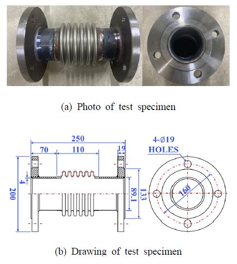
Fig. 2(a)는 실험시료의 사진이고 Fig. 2(b)는 도면이다. 연구의 대상은 주름 6개, 피치(pitch) 15 mm, 높이 15 mm의 U형 벨로즈로 길이는 110 mm이다. 실험시료의 중앙에 위치하며 양 끝은 50 mm 길이의 배관과 용접으로 연결되었다. 실험시료의 끝은 KS D 4308 플랜지가 적용되었다.
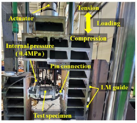
Fig. 3은 실험의 구성이다. 축 직각 방향으로 가해지는 외력에 의한 굽힘 변형이 벨로즈에 집중될 수 있도록 실험시료의 한쪽 끝을 UTM(universal testing machine)의 정반에 고정된 지그에 고정하고, 반대쪽 끝은 actuator에 고정한 지그와 핀으로 연결하였다. 그리고 LM 가이드를 이용하여 하중재하 방향 이외의 자유도를 구속하였다. 실험 전 실험시료의 내부에 물을 채우고 레귤레이터와 전기펌프를 이용하여 0.4 MPa(22)의 압력을 가한 후 실험 종료 시까지 유지하였다. 실험은 부산대학교 지진방재연구센터의 1000 kN UTM을 이용하여 수행되었다.
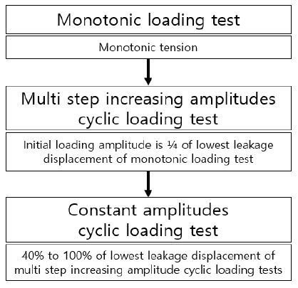
Fig. 4는 실험의 절차이다. 우선 단조하중재하실험을 수행한다. 단조하중재하실험의 최소누출변위의 25 %를 초기진폭으로 하여 점진증폭 반복하중재하실험을 수행한다. 그리고 점진증폭 반복하중재하실험의 누출이 발생한 사이클의 앞 사이클 중 낮은 값을 기준으로 고정진폭 반복하중재하실험을 수행한다. Fig. 4에서 단조하중재실험과 점진증폭 반복하중재하실험은 각각 구조성능과 내진성능을 검증하기 위한 실험이고, 고정진폭 반복하중재하실험은 저주기 피로 성능평가이다.
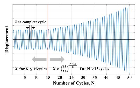
단조하중재하실험은 Fig. 3의 인장(tension) 방향으로 누출이 발생할 때까지 수행되었다. 점진증폭 반복하중재하실험은 식 (1)과 같이 초기진폭(X)에 대하여 15 사이클 반복하중재하 후 식 (2)에 의해 진폭의 크기를 증가하며 누출이 발생할 때까지 실험을 수행하였다. 여기서 초기진폭 15 사이클은 설계수준의 지진 1회를 의미한다(23). 식 (1)과 식 (2)에서 ∆l은 굽힘 변위이고 N은 사이클 수이다.
| (1) |
| (2) |
Fig. 5는 점진증폭 반복하중재하실험의 실험변위이력으로 배관 버팀대와 연결부의 내진실험방법인 ANSI/FM 1950(24)과 KS B 1528(25)을 참조하였다. 고정진폭 반복하중재하실험은 저주기 피로 수명을 유추하기 위해 수행하였다. 점진증폭 반복하중재하실험의 최소누출변위 이전 사이클의 단방향 최댓값을 100 %로 정의하고 40 %부터 100 %까지 10 % 간격의 진폭을 고려하였다.
단조하중재하실험과 점진증폭 반복하중재하실험은 모두 2회씩 수행하였으며, 고정진폭 반복하중재하실험은 각각의 입력진폭의 크기에 대해 1회씩 수행하였다. 모든 실험의 하중재하속도는 1 mm/s 이하이다.
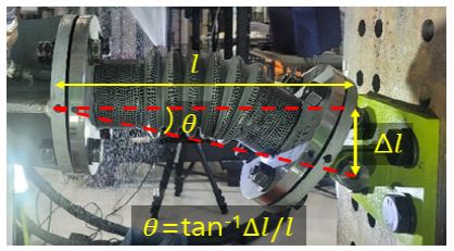
변형각은 지진분리이음에 요구되는 대표적인 성능이다(25,26). 따라서 이 논문에서는 Fig. 6과 같이 고정된 플랜지의 중심과 핀 연결부의 중심을 기준으로 변형각을 계산하였다. Fig. 6에서 l은 실험시료의 길이이고 ∆l은 굽힘 변위이며, θ는 변형각이다.
3. 실험 결과 및 분석
3.1 실험결과
Table 2는 굽힘 실험의 결과이다. 단조하중재하에 의한 누출변위(∆lf)는 237.0 mm와 248.7 mm로 차이는 4.8 %이고 누출변형각(θf)은 37.5°와 38.8°로 차이는 3.4 %이다. 점진증폭 반복하중재하실험의 누출변위는 126.0 mm와 130.5 mm로 차이는 3.5 %이고 변형각은 22.2°와 22.9°로 3.1 %의 차이가 있다. 차이는 식 (3)을 이용하여 계산하였다. 여기서 E1과 E2는 실험값이다.
| (3) |
단조하중재하실험의 최소 누출변위는 237.0 mm이므로 점진증폭 반복하중재하실험의 초기변위는 소수점 반올림하여 59.0 mm로 정의하였다. 고정진폭 반복하중재하실험의 입력진폭의 크기 100 %는 점진증폭 반복하중재하실험 최소누출변위가 발생한 위치의 앞 사이클의 크기인 122 mm이다. 입력진폭은 40 %에서부터 100 %까지 10 % 단위로 적용하였다. 각각의 입력진폭에 대한 변위와 변형각은 Table 2에 표시하였다. 입력진폭의 크기가 증가할수록 누출 사이클 수(Nf)는 증가한다. 고정진폭 반복하중재하실험의 Nf는 50 % 이상일 때 406 사이클 이하이고, 40 %일 때 1949 사이클이다.
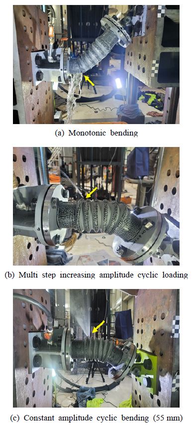
Fig. 7에서 각 실험에서의 누출 위치를 노란색 화살표로 표시하였다. Fig. 7(a)는 단조하중재하실험의 누출 위치이며 Fig. 7(b)와 Fig. 7(c)는 각각 점진증폭 반복하중재하실험과 고정진폭 반복하중재하실험의 누출위치이다. 단조하중재하실험에서 누출은 벨로즈와 배관을 연결하는 용접부의 손상으로 나타났다. 그러나 점진증폭 반복하중재하실험과 고정진폭 반복하중재하실험의 경우, 벨로즈의 주름에서 관통균열에 의한 누출이 관찰되었다. 이와 같이 단조하중과 반복하중에 의한 손상 위치와 형상은 서로 다르게 나타났다.
3.2 하중‒변위 상관관계
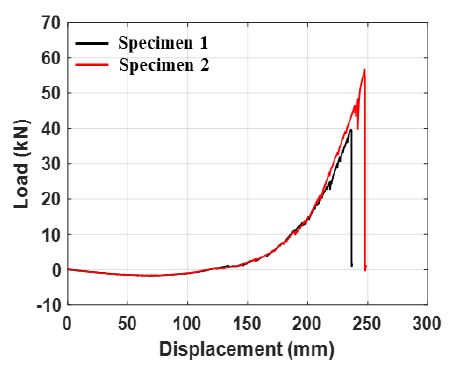
Fig. 8은 단조하중재하실험으로부터 계측된 하중응답과 변위응답의 상관관계 그래프이다. 단조하중에 의한 하중‒변위의 경향은 유사하며 누출변위의 차이는 4.8 %로 크지 않다. 그러나 최대하중은 각각 39.8 kN과 56.8 kN으로 35.2 %의 큰 차이가 있다.
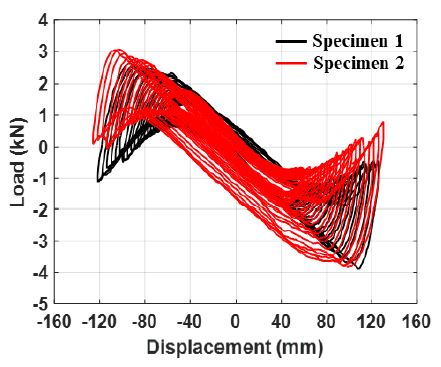
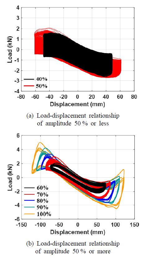
Fig. 9는 점진증폭 반복하중재하실험의 결과이고 Fig. 10은 고정진폭 반복하중재하실험의 결과이다. Fig. 9와 Fig. 10(b)의 경향은 유사함을 알 수 있다. 그러나 Fig. 10(a)과 같이 Nf가 400 사이클 이상인 50 % 이하 진폭의 고정진폭 반복하중재하실험들의 경우, 사이클의 수가 증가함에 따라 하중저하가 발생하는 것이 관찰되었다. Figs. 8 ~ 10의 하중과 변위는 액추에이터의 하중계(load cell)와 변위계(displacement meter)에서 계측된 응답이다.
3.3 저주기 피로 성능
이 연구에서 내진성능평가를 위해 참고한 배관 흔들림 방지 버팀대의 실험방법인 FM 1950에 따르면 초기하중은 예상되는 한계하중의 50 %를 초과하지 않아야 한다. Table 2에서 입력진폭 50 % 이상의 가력변위에서 Nf는 현저히 줄어든다. 피로파괴는 물체가 작은 힘을 반복하여 받음으로써 균열이 발생하고 마침내 파괴되는 현상을 말한다. 피로현상 중에서 낮은 반복횟수의 피로손상을 저주기 피로로 정의한다. 일반적으로 사이클의 수가 1000 ~ 10 000회 이하일 경우가 저주기 피로에 해당한다(27). 따라서 이 연구에서는 입력진폭의 크기가 50 % 이상인 경우에 대하여 저주기 피로 수명을 분석하였다.
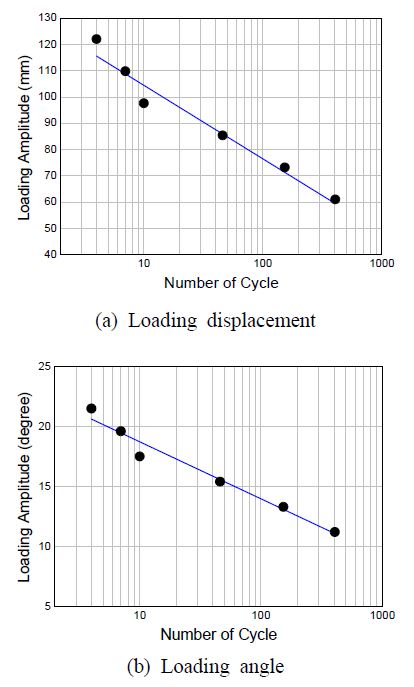
Fig. 11은 3ply 벨로즈형 신축관이음 저주기 피로 거동을 나타낸 것이다. Fig. 11(a)와 식 (4)는 변위와 Nf의 저주기 피로 곡선이고, Fig. 11(b)와 식 (5)는 변형각과 Nf의 저주기 피로 곡선이다. 여기서 ∆lf는 누출변위이고, θf는 누출변형각이다.
| (4) |
| (5) |
결정계수(R2)가 1에 가까울수록 회귀선이 자료와 잘 일치하는 것을 의미한다. 식 (4)와 식 (5)에서 R2은 0.96 이상으로 Nf와 입력진폭의 크기는 매우 높은 신뢰도를 나타내고 있다.
3.4 한계성능분석
Table 3은 단조하중재하실험과 점진증폭 반복하중재하실험의 누출점을 비교한 것이다. 평균, 최대, 최소에 대하여 누출점을 비교하였으며 소수점 둘째 자리까지 반올림하여 표시하였다. 그 결과 변위의 비는 0.52와 0.53이고 변형각은 모두 0.59로 나타났다. 따라서 평균값을 대표값으로 하여 3ply 벨로즈형 신축관이음의 내진성능을 분석하였다.
Table 4는 단조하중재하실험과 점진증폭 반복하중재하실험의 평균 누출점을 대표값으로 하여 고정진폭 반복하중재하실험의 입력진폭 50 %의 누출점과 비교한 것이다. Table 4에서 고정진폭 반복하중재하실험의 입력진폭 50 %는 단조하중재하실험의 누출변위의 25 %이고, 변형각의 경우 29 %이다. 따라서 이 연구에서 사용한 3ply 벨로즈형 신축관이음의 경우 단조하중에 대한 누출변위의 25 % 또는 변형각의 29 % 이상의 크기의 외력에서 저주기 피로 거동이 발생하는 것으로 판단된다. 그러므로 내진성능평가를 위한 점진증폭 반복하중재하실험의 초기진폭의 크기가 저주기 피로에 의한 소성변형의 누적이 발생하지 않을 것을 목적으로 한다면, 단조하중에 의한 누출변위의 25 % 이하가 되어야 할 것으로 판단된다. Table 4로부터 단조하중재하실험의 누출변위의 약 50 % 수준이 점진증폭 반복하중재하실험의 누출변위이며, 저주기 피로현상이 관찰되는 변위는 약 25 %임을 알 수 있다. 그리고 단조하중재하실험 누출변형각의 약 60 %가 점진증폭 반복하중재하실험의 누출변형각이며, 저주기 피로가 관찰되기 시작하는 변형각의 크기는 단조하중재하실험 누출변형각의 약 30 % 수준으로 판단된다.
Table 4로부터, 이 연구에서 사용한 3ply 벨로즈형 신축관이음의 단방향 굽힘 변형에 대한 변위한계는 242.9 mm, 38.2º이고, 지진으로 인한 반복되는 굽힘 변형에 대한 변위한계와 변형각한계는 각각 128.2 mm와 22.6º이다.
4. 결 론
이 연구에서는 벨로즈형 신축관이음의 단조하중재하실험과 점진증폭 반복하중재하실험으로 내진성능을 평가하였으며, 고정진폭 반복하중재하실험으로 저주기 피로의 영향을 분석하였다.
점진증폭 반복하중재하실험의 누출변위는 단조하중재하실험의 누출변위의 약 50 % 수준이고, 저주기 피로현상이 관찰되는 변위는 단조하중재하실험 누출변위의 약 25 %이다. 단조하중재하실험 누출변형각의 약 60 %가 점진증폭 반복하중재하실험의 누출변형각이고, 저주기 피로가 관찰되기 시작하는 변형각의 크기는 단조하중재하실험 누출변형각의 약 30 % 수준이다.
이 연구에서 사용한 점진증폭 반복하중재하실험에서 초기진폭에 의한 15 사이클은 지진하중 1회를 의미한다. 그러므로 이 단계에서 누출이나 손상이 발생하지 아니하여야 한다. 따라서 초기진폭의 크기는 저주기 피로에 의한 누적소성변형이 최소화되어야 할 것으로 판단된다. 이 연구의 결과에 의하여 점진증폭 반복하중재하실험의 초기진폭의 크기는 단조하중재하실험 누출변위의 25 % 이하 또는 누출변형각의 30 % 이하가 적절할 것으로 판단된다.
이 연구의 결과는 벨로즈형 신축이음관의 내진설계 자료로 활용될 수 있을 것이다. 또한 벨로즈형 신축관이음의 성능검증 및 실험적 연구를 수행하고자 할 때 위상차에 의한 지진상대 변형을 고려하기 위한 기초 자료로 활용될 수 있을 것이다.
Acknowledgments
이 연구는 산업통상자원부(MOTIE)와 한국에너지기술평가원(KETEP)의 지원을 받아 수행한 연구 과제입니다(과제번호 20217910100150).
References
- The Federal Emergency Management Agency (FEMA), 2012, FEMA E-74, Reducing the Risks of Nonstructural Earthquake Damage ‒ A Practical Guide, FEMA, Washington, D. C., USA.
- American Society of Civil Engineers/Structural Engineering Institute (ASCE/SEI), 2017, ASCE 7-16, Minimum Design Loads and Associated Criteria for Buildings and Other Structures, ASCE, Reston, USA.
- National Fire Protection Association (NFPA), 2013, NFPA 13, Standard for the Installation of Sprinkler Systems, NFPA, Quincy, USA.
- Ministry of the Interior and Safety (MOIS), 2016, Seismic Design Criteria of Fire Fighting Facilities, MOIS, Sejong, Korea.
- Miki, C., Kobayashi T., Oguchi, N., Uchida, T., Suganuma, A. and Katoh, A., 2000, Deformation and Fracture Properties of Steel Pipes Bend with Internal Pressure Subjected to In-plane Bending, Proceedings of the 12th World Conference on Earthquake Engineering, Auckland, New Zealand.
-
Jang, H. W., Hahm, D. G., Jung, J. W. and Hong, J. W., 2018, Effective Numerical Approach to Assess Low-cycle Fatigue Behavior of Pipe Elbows, Nuclear Engineering and Technology, Vol. 50, No. 5, pp. 758~766.
[https://doi.org/10.1016/j.net.2018.01.020]

-
Takahashi, K., Ando, K., Matsuo, K. and Urabe, Y., 2014, Estimation of Low-cycle Fatigue Life of Elbow Pipes Considering the Multi-axial Stress Effect, Journal of Pressure Vessel Technology, Vol. 136, No. 4, Article No. 041405.
[https://doi.org/10.1115/1.4026903]

-
Takahashi, K., Watanabe, S., Ando, K., Urabe, Y., Hidaka, A., Hisatsune, M. and Miyazaki, K., 2009, Low Cycle Fatigue Behaviors of Elbow Pipe with Local Wall Thinning, Nuclear Engineering and Design, Vol. 239, No. 12, pp. 2719~2727.
[https://doi.org/10.1016/j.nucengdes.2009.09.011]

-
Kim, S. W., Jeon, B. G., Ahn, S. W. and Wi, S. W., 2021, Seismic Behavior of Riser Pipes with Pressure and Groove Joints using an In-plane Cyclic Loading Test, Journal of Building Engineering, Vol. 34, Article No. 101911.
[https://doi.org/10.1016/j.jobe.2020.101911]

-
Kim, S. W., Yun, D. W., Kim, J. B., Jeon, B. G. and Choi, Y. A., 2021, Behavior Analysis of Riser Pipe with Pressure Joints under Cyclic Loading Conditions using Imaging System, Transactions of the Korean Society for Noise and Vibration Engineering, Vol. 31, No. 2, pp. 185~194.
[https://doi.org/10.5050/KSNVE.2021.31.2.185]

-
Kim, S. W., Yun, D. W., Jeon, B. G. and Kim, J. B., 2022, Seismic Performance Evaluation of a Vertical Pipe Connected with Rigid Groove Joints using a System and a Component, Structures, Vol. 36, pp. 691~702.
[https://doi.org/10.1016/j.istruc.2021.12.046]

-
Soroushian, S., Zaghi, A. E., Maragakis, M., Echevarria, A., Tian, Y. and Filiatrault, A., 2015, Analytical Seismic Fragility Analyses of Fire Sprinkler Piping Systems with Threaded Joints, Earthquake Spectra, Vol. 32, No. 2, pp. 1125~1155.
[https://doi.org/10.1193/083112EQS277M]

-
Karamanos, S. A., Keil, B. and Card, R. J., 2014, Seismic Design of Buried Steel Water Pipelines, Proceedings of the Pipelines 2014: From Underground to the Forefront of Innovation and Sustainability, Portland, USA, pp. 1005~1019.
[https://doi.org/10.1061/9780784413692.091]

-
Yousife, D. F., Aldefae, A. H., Zubaidi, S. L., Humaish, W. H. and Sinichenko, E. K., 2021, Static and Seismic Performance of Buried Pipelines: A review, Proceedings of the Second International Conference on Geotechnical Engineering - Iraq (ICGE 2021), Akre, Iraq, Vol. 318, 01011.
[https://doi.org/10.1051/e3sconf/202131801011]

- Donald, B., 2013, Understanding the Seismic Vulnerability of Water Systems.
- Wham, B. P., O’Rouke, T. D., Stewart, H. E., Bond, T. K. and Pariya-Ekkasut, C., 2016, Large-scale Testing of JFE Steel Pipe Crossing Faults: Testing of SPF Wave Feature to Resist Fault Rupture, Cornell University, Ithaca, NY, USA.
-
Edkins, D. J., Orense, R. P. and Henry, R. S., 2021, Seismic Simulation Testing of PVC-U Pipe and Proposed Design Prediction Tool for Joint Performance, Journal of Pipeline Systems Engineering and Practice, Vol. 12, No. 2, 04021007.
[https://doi.org/10.1061/(ASCE)PS.1949-1204.0000538]

-
Lv, Y., Liang, L. R., Li, Y. W., Chen, Y. and Chouw, N., 2021, Experimental and Finite-element Study of Buried Pipes Connected by Bellow Joint under Axial Cyclic Loading, Journal of Pipeline Systems Engineering and Practice, Vol. 12, No. 1, 04020069.
[https://doi.org/10.1061/(ASCE)PS.1949-1204.0000524]

-
Lv. Y., Liang, L. R., Li, Y. W., Chen, Y. and Chouw, N., 2021, Experimental and Finite-element Studies of Buried Pipes Connected by a Bellow Joint under Cyclic Shear Loading, Journal of Pipeline Systems Engineering and Practice, Vol. 12, No. 4, 04021057.
[https://doi.org/10.1061/(ASCE)PS.1949-1204.0000605]

-
Xiang, X. M., Lu, G., Li, Z. X. and Lv, Y., 2017, Finite Element Analysis and Experimental Study on a Bellows Joint, Engineering Structures, Vol. 151, pp. 584~598.
[https://doi.org/10.1016/j.engstruct.2017.08.034]

-
Yun, D. W., Jeon, B. G., Kim, S. W., Yu, J. S. and Ju, B. S., 2021, Low Cycle Fatigue Reliability Tests for Earthquake and Subsidence-resistant Performance Evaluation for Bellows Joint System, Korean Society for Advanced Composite Structures, Vol. 12, No. 6, pp. 64~70.
[https://doi.org/10.11004/kosacs.2021.12.6.064]

- Korea Gas Safety Corporation (KGS), 2021, KGS FU551, Facility/Technical/Inspection Code for Urban Gas using Facilities, KGS, Eumseong, Korea.
-
Malhotra, P. K., Sensery, P. E., Braga, A. C. and Allard, R. L., 2003, Testing Sprinkler-pipe Seismic-brace Components, Earthquake Spectra, Vol. 19, No. 1, pp. 87~109.
[https://doi.org/10.1193/1.1543160]

- American National Standards Institute (ANSI), 2016, ANSI/FM Approvals 1950, American National Standard for Seismic Sway Braces for Pipe, Tubing and Conduit, ANSI, Washington, DC, USA.
- Korea Agency for Technology and Standards (KATS), 2019, KS B 1528, Seismic Safety Test Method for Pipe Connecting Parts, KATS, Eumseong, Korea.
- International Organization for Standardization (ISO), 2020, ISO 16134, Earthquake-resistant and Subsidence-resistant Design of Ductile Iron Pipelines, ISO, Geneva, Switzerland.
- Architectural Institute of Korea (AIK), 2008, Dictionary of Building Structures, AIK, Seoul, Korea.

Bub-Gyu Jeon received his Ph.D. degree from Pusan National University with the topic related with seismic fragility evaluation of base isolated nuclear power plant piping system. He is currently the research and strategy team manager in Seismic Research and Test Center. His research interests include seismic evaluation of nonstructural elements and seismic behavior of internal pressured piping system.

Sung-Wan Kim received his Ph.D. degree from Pusan National University with the title of “Health Monitoring of Civil Structures Using Image Measurement System.” He is currently the research professor in Seismic Research and Test Center. His research interests include structural health monitoring and ambient vibration tests of civil infrastructures.


