고정익 항공기용 연료파일런 지상진동시험
© The Korean Society for Noise and Vibration Engineering
Abstract
The ground vibration test is a method of experimentally obtaining the dynamic characteristics of a structure, such as the natural frequency and natural vibration mode. It aims to verify the reliability of the numerical analysis model by comparing the numerical analysis results with the ground vibration test results or improve the numerical analysis model by reflecting on the test results. In this study, the reliability of the numerical analysis model of the fuel pylon for an aircraft was verified by comparing the natural frequency and natural vibration mode of the fuel pylon obtained through the ground vibration test and numerical analysis. This study describes the main test equipment used to perform the ground vibration test, test set-up, and test model to verify the natural vibration mode of the specimen. After setting up the ground vibration test, the points at which the main vibration modes are well excitable were determined through a preliminary test. Accordingly, the dynamic response data were collected at the corresponding points by providing excitation with an impact hammer. Finally, a frequency response analysis was performed on the response acceleration acquired from the accelerometer to identify the natural frequency and natural vibration mode of the specimen. Subsequently, the reliability of the numerical analysis model of the specimen was verified by comparing the ground vibration test results with the natural frequency and vibration mode calculated through the numerical analysis using the finite element model.
Keywords:
Bungee Cord, Frequency Response Analysis, Fuel Pylon, Ground Vibration Test키워드:
번지코드, 주파수 응답해석, 연료파일런, 지상진동시험1. 서 론
일반적으로 항공기의 동특성이나 동적거동을 파악하기 위해서 유한요소 모델(finite element model, 이하 FEM)과 같은 수치해석 모델을 사용한다. 그런데, 수치해석 모델을 생성하는 과정에서 모델 단순화나 가정 등이 반영되므로 수치해석 모델을 실제 구조물과 완벽히 동일하게 만드는 것은 불가능하다. 이런 이유로 수치해석 모델을 사용하여 예측한 구조물의 동특성 결과와 시험으로부터 획득한 결과를 비교하여 수치해석 모델의 신뢰성을 검증해야 할 필요가 있다. 또한, 수치해석 결과가 시험결과와 많은 차이를 보이는 경우에는 시험결과를 반영하여 수치해석 모델을 개선해야 한다. 여기서, 고유주파수나 고유 진동모드와 같은 구조물의 동특성을 실험적인 방법으로 구하는 방법이 지상진동시험(ground vibration test, 이하 GVT)이며, 지상진동시험은 수치해석 모델의 신뢰성을 검증하거나 개선하는 데 이용된다. 이와 관련된 연구로, Yoo 등(1)은 항공기 지상진동시험 결과를 이용하여 유한요소 모델에 대한 개선 방법을 연구하였다(1). Paek and Choi(2)는 KC-100 항공기의 지상진동시험을 통해서 KC-100의 고유 진동모드 특성을 파악하고, 시험결과를 사용하여 유한요소 모델을 보정하였다. Lee 등(3)은 고고도 태양광무인기에 대한 고유진동 특성을 파악하여 동특성 해석용 수치해석 모델의 개선에 대한 연구를 수행하였고, Jeon 등(4)은 스마트무인기의 자유진동특성과 강제진동특성을 실험적으로 규명하기 위해 지상진동시험과 강제진동시험을 수행하였다(4). Byun 등(5,6)은 KF-16의 동특성을 실험적으로 규명하고, 플러터 해석을 통해서 외부장착물과 항공기와의 적합성 입증에 대한 연구를 수행하였다. 또한, Lim 등(7)은 지상진동시험을 통해 확보한 데이터를 이용하여 외부장착물에 대한 공탄성학적 적합성을 입증하는 방안에 대한 연구를 수행하였다. 이외에도, 한국형기동헬기에 대한 지상진동시험 및 수치해석 모델의 보정에 관한 연구(8)가 수행된 바 있으며, 쿼드로터(quad rotor) 플랫폼에 대해 모달시험(modal test)을 통한 진동특성 분석 및 공진 회피 설계연구(9)와 같이 지상진동시험을 수행하여 대상 구조물의 동특성을 파악하고 수치해석 결과와의 상관관계(corelation)를 분석하여 동특성 해석에 사용하는 수치해석 모델에 대한 개선 연구가 꾸준히 진행되어왔다.
이 연구에서는 항공기용 연료파일런(fuel pylon)의 수치해석 모델에 대한 검증을 목적으로 수행된 지상진동시험 결과를 제시한다. 이를 위해, 지상진동시험을 위한 시험설치시 시험체 강체모드와 시험체 고유 진동모드 간의 간섭이 발생하지 않도록 번지코드(bungee cord)를 사용하여 시험체의 자유경계 조건을 구현하였다. 시험설치 후에는, 사전시험을 통해서 주요 진동모드가 잘 가진될 수 있는 지점을 결정하고, 임팩트 해머(impact hammer)로 가진하였다. 그리고, 가속계 설치 지점들에서 획득한 응답가속도에 대해 주파수 응답해석을 수행하여 시험체의 고유주파수와 고유 진동모드를 구하였다. 최종적으로, 지상진동시험 결과와 수치해석을 통해 예측한 고유주파수 및 고유 진동모드 결과를 비교하여 시험체에 대한 수치해석 모델의 신뢰성을 검증하였다.
2. 시험 구성 및 수행
2.1 시험체 설치
Fig. 1은 연료파일런의 지상진동시험을 수행하기 위한 시험설치 형상이다. 시험체는 항공기의 주익과 체결되는 세 지점에서 번지코드를 사용하여 지지하도록 하였다. 여기서, 시험체의 자유경계 조건을 잘 모사하기 위해서는 시험체 강체모드 주파수가 시험체 최저차 고유진동수의 절반을 넘지 않도록 해야 하는데(10), 이를 고려하여 이 연구의 지상진동시험에서는 직경 18 mm와 20 mm 번지코드를 사용하였다. 참고로, 이 논문에서는 보안문제로 인하여 시험체의 외곽형상(outer mold line, 이하 OML)을 사용하여 시험설치 등을 설명하였다.

Test set-up for GVT of fuel pylon
Fig. 2는 지상진동시험에 사용된 번지코드와 직경 18 mm와 20 mm 번지코드 물성선도를 보여주고 있다. Table 1은 대상 시험체의 최소 주파수 절반을 넘지 않는 강성 요구조건과 시험체 중량을 반영하여 계산된 번지코드 강성값이다. 검토 결과, 번지코드의 강성은 시험체 1차 고유 진동수의 절반 이하로 파악되었고, 해당 번지코드를 적용한 시험체의 강체모드는 시험체 고유 진동모드에 영향을 주지 않는 것으로 판단되었다.

Bungee cord and material property curve

Stiffness of bungee cord for GVT
2.2 시험구성 및 수행
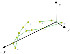
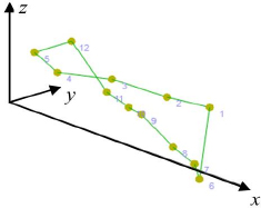
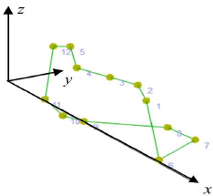
Fig. 3은 연료파일런의 지상진동시험을 수행하기 위한 시험 구성으로써, 시험에 사용되는 주요장비는 시험데이터 획득을 위한 데이터획득장비, 가속도계 그리고 시험체를 가진하는데 사용되는 임팩트 해머 등이다. Table 2는 지상진동시험에 사용되는 주요 장비를 보여주고 있다. Fig. 4와 같이 총 10개의 가속도계를 시험체에 설치하였는데, 시험 전에 가속도계에 대한 교정을 진행하면서 가속도계 정상작동 여부와 감도(sensitivity)를 확인하였다. 그리고, Fig. 5와 같이 가속도계 설치 위치들을 연결하여 시험체의 고유 진동모드 확인에 사용되는 시험모델(test model)을 생성하였다.

Test configuration diagram for GVT
Test equipment for GVT

Locations of accelerometers

Test model of fuel pylon for GVT
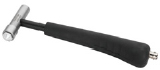
Fig. 6은 시험체에 가속도계를 설치한 후, 가속도계 케이블을 데이터획득장비와 연결하여 지상진동시험 수행을 위한 시험설치가 완료된 상태를 보여주고 있다. 시험설치가 완료된 후에는 사전점검을 통해서 시험체의 고유 진동모드가 잘 가진될 수 있는 위치를 결정하였다. 그리고, 임팩트 해머로 시험체를 가진하여 가속도계 설치 위치들에서 시험체의 동적응답을 획득하였다. Fig. 7은 시험체 가진 위치를 보여주고 있다.

Completion of preparation for GVT

Impact location for obtaining the dynamic data of the test specimen
3. 시험 결과
Table 3은 가속도계에서 획득한 신호들에 대한 기여도(coherence) 분석 결과이다. 기여도는 모달 테스트를 통해 측정된 데이터의 신뢰성을 가름하는 척도로 쓰이며, 1에 가까울수록 가진력이 잘 전달되었음을 의미한다. Table 3에서 대부분의 위치에서 기여는 1.0으로 파악되고 있으나, 8번 x 방향과 10번 x 방향에서는 기여도가 0.9 이하로 파악되었다.
Coherence of each accelerometer
Fig. 8(a)는 기여도 0.9 이상인 가속도계 데이터를 반영하여 주파수 응답해석을 수행한 결과이다. 그리고, Fig. 8(b)는 1차, 2차 그리고 3차 고유 진동모드가 나타나는 주파수에서의 위상변화를 보여주고 있으며, Fig. 8(c)에서는 해당 고유주파수에서 기여도가 0.9 이상인 것을 확인할 수 있다. 따라서, 주파수 응답해석에서 파악되는 94.0 Hz, 159.7 Hz, 207.8 Hz의 모드는 시험체의 고유 진동모드로 파악된다.

Results of frequency response analysis
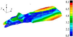
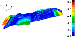
Fig. 9는 고유모드 해석에 사용된 시험체의 유한요소 모델(finite element model, 이하 FEM)이다. 해당 유한요소 모델의 중량은 90.85 N이고, 2 450 000개 절점과 BEAM, QUAD4, TETRA 요소 등을 사용하여 총 1 530 000개의 요소로 구성되었다. 유한요소 모델에 적용된 물성 정보와 구체적인 수치는 Table 4와 같다.

Finite element model of the test specimen
Material property of FEM
고유모드 해석을 통해서, 1차 고유주파수는 91.7 Hz, 2차 고유 진동수는 155.4 Hz, 3차 고유 진동수는 195.5 Hz로 계산되었다. 참고로, 고유모드 해석은 자유경계 조건을 적용하였고, 전/후처리 및 솔버(solver)는 MSC patran/nastran을 사용하였다.
Table 5는 수치해석과 시험으로부터 구해진 연료파일런의 고유 진동수를 비교한 것이다. 그 결과, 수치해석과 시험결과 사이의 고유 진동수 오차는 1차와 2차 주파수는 2 % ~ 3 %, 3차 주파수에서는 약 6 % 수준으로 파악되었다.
Error value of the main vibration mode
Table 6은 수치해석과 지상진동시험을 통해 예측되는 고유 진동모드를 비교한 것이다. 연료파일런의 1차 모드는 1차 굽힘모드, 2차 모드는 비틀림모드, 3차 모드는 굽힘모드와 비틀림 모드가 모두 나타나는 혼합모드로 파악되었는데, 모드형상 비교 결과, 수치해석을 통해 계산된 고유 진동모드와 지상진동시험으로부터 획득한 고유 진동모드가 동일한 것을 확인할 수 있다.
Mode comparison between analysis and GVT
4. 결 론
이 연구에서는 항공기용 연료파일런의 지상진동시험을 통해 획득한 고유 진동모드 결과와 유한요소 모델을 이용한 고유모드 해석결과를 비교하여 항공기용 연료 파일런의 수치해석 모델에 대한 신뢰성을 검증하였다.
지상진동시험을 수행하기 위해 번지코드를 사용하여 시험체에 대한 자유경계 조건을 구현하였고, 사전 시험을 통해 결정한 시험체 가진 위치를 임팩트 해머로 가진하여 동적응답을 획득하고, 주파수 응답해석을 수행하였다. 시험결과, 연료파일런의 1차 모드는 1차 굽힘모드, 2차 모드는 비틀림모드 그리고 3차 모드는 굽힘모드와 비틀림 모드가 모두 나타나는 혼합모드로 파악되었다. 또한, 수치해석과 지상진동시험을 통해 예측된 고유 진동모드가 상호 동일함을 확인하였고, 수치해석 결과와 시험 획득값 사이의 1차, 2차, 3차 주파수 오차는 2 % ~ 6 %로 파악되었다. 따라서, 이 연구를 통해 항공기용 연료파일런의 수치해석 모델에 대한 신뢰성을 검증하였고, 향후 연료파일런의 유한요소 모델을 개선하여 현재보다 수치해석 결과의 신뢰성을 향상시킬 수 있을 것으로 사료된다.
References
- Yoo, H.-J., Byun, K.-H. and Park, K.-Y., 1998, The Ground Vibration Test on an Aircraft and FE Model Update, Journal of KSNVE, Vol. 8, No. 4, pp. 690~699.
- Paek, S.-K. and Choi, Y.-J., 2011, Flutter Analysis Model Tuning of KC-100 Aircraft with the Ground Vibration Test Results, Proceedings of the KSNVE Annual Autumn Conference, pp. 191~195.
-
Lee, S.-W., Park, S.-W. and Shin, J.-W., 2017, Flutter Analysis of a High-altitude Solar Powered UAV, Transactions of the Korean Society of Mechanical Engineers A, Vol. 41, No. 12, pp. 1215~1221.
[https://doi.org/10.3795/KSME-A.2017.41.12.1215]

-
Jeon, B.-H., Kang, H.-W., Lee, J.-J. and Lee, Y.-S., 2010, Ground Vibration Tests of Smart UAV Airframe Structure, Journal of the Korean Society for Aeronautical and Space Sciences, Vol. 38, No. 5, pp. 482~489.
[https://doi.org/10.5139/JKSAS.2010.38.5.482]
-
Byun, K.-H., Park, C.-Y. and Kim, J.-H., 2005, Ground Vibration Test of KF-16D, Journal of the Korean Society for Aeronautical and Space Sciences, Vol. 33, No. 5, pp. 41~49.
[https://doi.org/10.5139/JKSAS.2005.33.5.041]
-
Byun, K.-H. and Jun, S.-M., 2006, Flutter Analysis of F-16 Aircraft Using Test Modal Data, Journal of the Korean Society for Aeronautical and Space Sciences, Vol. 34, No. 4, pp. 76~82.
[https://doi.org/10.5139/JKSAS.2006.34.4.076]
-
Lim, H. T., Kwon, J. R., Byun, K. H., Kim, H. J. and Kim, J. H., 2017, Aeroelastic Compatibility Substantiation of Aircraft External Stores Using the Dynamic Characteristic Data from Ground Vibration Test, Journal of the Korean Society for Aeronautical and Space Sciences, Vol. 45, No. 4, pp. 269~275.
[https://doi.org/10.5139/JKSAS.2017.45.4.269]
-
Kim, S.-H., Kwak, D.-I., Jung, S.-U., Choi, J.-H. and Kim, J.-H., 2013, Ground Vibration Test for Korean Utility Helicopter, Journal of the Korean Society for Aeronautical and Space Sciences, Vol. 41, No. 6, pp. 495~501.
[https://doi.org/10.5139/JKSAS.2013.41.6.495]
-
Kim, M., Kim. J., Byun, Y., Kim, J. and Kang, B., 2016, Study on Analysis of Vibration Characteristics and Modal Test for a Quad-Rotor Drone, Journal of the Korean Society for Precision Engineering, Vol. 33, No. 9, pp. 707~714.
[https://doi.org/10.7736/KSPE.2016.33.9.707]
- United States Military, 1993, Airplane Strength and Rigidity: Vibration, Flutter, and Divergence, Military Specification MIL-A-8870C.

Sang-hwan Cho received the B.S. and M.S. degrees in the Dept. of mechanical engineering from Dankook University. He is currently a Researcher in Hanwha Aerospace company. His research interests are in the aircraft fuel system design and testing.

Hyun-kyung Choi received the B.S. and M.S. degrees in the Dept. of Aerospace engineering from Jeonbuk National University. She is currently a Researcher in Hanwha Aerospace company. Her research interests are in the aircraft fuel system design and testing.

Young-shin Kim has received M.S. degree of aerospace engineering from konkuk university in south korea. He is researching core technologies to develop sub-system of aerospace sector.

Sungchan Kim received the B.S. and M.S. degrees in Korea Aerospace University in 1988 and 1998, respectively, and the Ph.D. degree from Chungnam National University in 2009. He worked at Korea Aerospace Industry for T-50 supersonic jet trainer development as structural design engineer from 1995 to 2000. Since 2000, he has been working at Korea Aerospace Research Institute, where he is currently a principal researcher. His research interests are in the aircraft structural design and structural testing.

Hyun-gi Kim received the B.S., M.S. and Ph.D degrees from the department of mechanical engineering, Seoul National University in 2000, 2002 and 2006, respectively. He worked at Hyundai Heavy Industry as structural analysis engineer from 2006 to 2007. Since 2008, he has been working at Korea Aerospace Research Institute. His research interests are in the structural analysis and optimization.