Z-드라이브 프로펠러용 탄성커플링의 설계와 동특성
ⓒ The Korean Society for Noise and Vibration Engineering
Abstract
Propulsion shafting system applying diesel engine with reduction gear as prime mover generally installs an elastic coupling between the engine and the intermediate shaft. This coupling normally isolates the vibratory torque excited by diesel engine or the excess transient torque and moment occurring due to external impact. Hence elastic coupling allows the diesel engine and reduction gear to operate safely. In this paper, repeated breakdown of the elastic coupling occurred on a skimmer vessel propulsion shafting due to unknown vibration during sea trial. The authors investigated the probabilities and causes of the elastic coupling failure thru global vibration measurement and past incident analysis.
Keywords:
Flexible Coupling, Self-excited Torsional Vibration키워드:
탄성커플링, 자려 비틀림진동1. 서 론
방제선과 터그보트와 같은 해상 작업과 지원 목적으로 사용되는 소형 선박은 운항 시 방향 전환을 쉽게 하고 작업 시 큰 추력을 발생시키기 위하여 2기 2축의 Z-드라이브 프로펠러를 추진기관으로 이용하고 있다. 이러한 선박은 주 기관과 Z-드라이브 프로펠러 사이가 상당히 떨어져 있고 높이가 다른 경사면에 배치되므로 긴 중간축과 카단축을 이용하여 동력을 전달하도록 설계되어 있다. 그리고 주 기관인 디젤엔진에서 발생하는 비틀림진동 토크와 클러치 탈, 부착 시 과도한 토크변동을 줄이기 위하여 주 기관과 중간축 사이에 고성능의 탄성커플링을 적용한다. 이 연구에서는 초기 설계 제작된 탄성커플링이 시운전 중 자려 비틀림진동으로 인하여 계속되는 절손사고로 인하여 두 차례에 걸친 설계변경을 통해서 개선하였으며 이때 탄성커플링과 추진시스템의 동적인 특성을 확인하였으며 추진시스템의 사고방지를 위한 설계에 활용하고자 한다.
2. 축의 배치 및 비틀림진동의 이론 해석
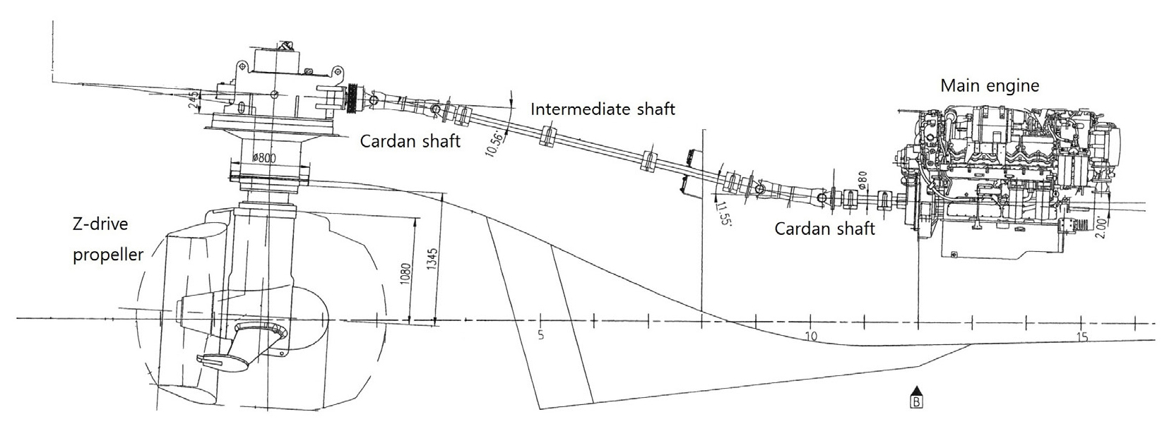
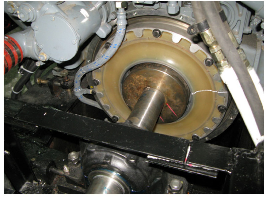
150톤급 방제선에 적용된 축의 배치는 Fig. 1과 같으며 디젤엔진의 동력을 Z-프로펠러까지 전달하기 위해 긴 축으로 연결되어 있고 감속기는 덕트형 프로펠러 상부에 위치하고 있다. 여기서 프로펠러는 360° 회전이 가능하여 선박의 방향전환이나 필요한 방향으로 추력을 발생할 수 있다. 그리고 주 기관인 디젤엔진 바로 후미는 Fig. 2와 같이 고무형 탄성 커플링 A가 설치되어 있으며 특징으로는 공간을 줄이기 위해 외륜은 플라위 휠에 내륜은 중간축에 직접 연결되어 있다. 3축(x, y, z: 전후, 좌우, 상하) 변형 허용한도가 크지 않은 구조다. 또한 이 커플링은 감속기어에 전달되는 진동토크와 각가속도를 줄여 기어의 햄머링(hammering)과 채터링(chattering)을 줄일 목적으로 필수적으로 설치해야 할 동력전달 부품이다. Table 1은 추진축계를 구성하는 부품들의 요목을 보인다.
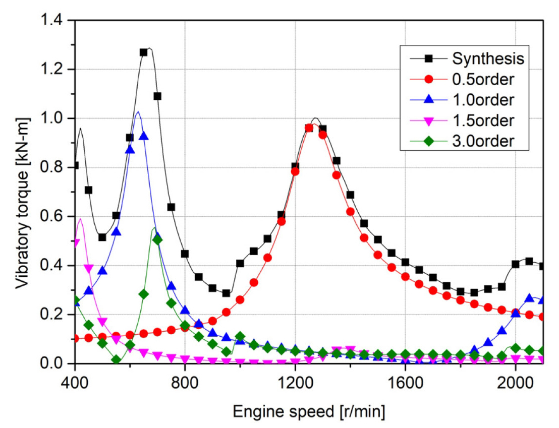
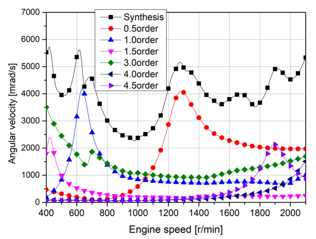
탄성커플링 제작사에서 제공한 자료를(2) 참조하여 추진축계를 27개의 집중 질량계로 모델링하고 탄성커플링의 강성을 100 % 엔진부하로 가정하여 비틀림진동 해석을 자체 S/W를 이용 수행하였다. 여기서 문제가 되었던 1절 고유진동수는 631 cycles/min이고, 탄성커플링의 진동특성을 확인하기 위하여 한 실린더 연소 실패 시 진동토크와 각속도 변동을 Fig. 3과 Fig. 4에 각각 보인다. 이때 0.5차, 1차 공진은 1260 r/min, 630 r/min에서 각각 일어난다.
3. 추진축계의 비틀림 진동측정 및 설계변경
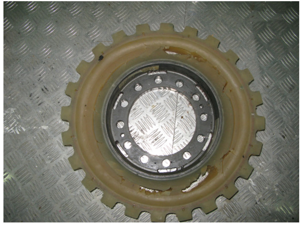
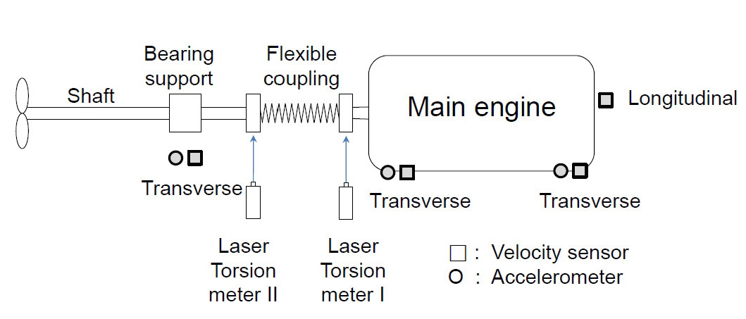
시운전 중 Fig. 5와 같이 탄성커플링 고무분분의 파손이 반복되어 원인을 조사하기 위하여 Fig. 6과 같이 진동측정 장비를 배치하였다. 우선 비틀림진동을 확인하기 위하여 탄성커플링의 엔진 측과 중간축에 각각 레이저 토숀메터를 설치하여 각속도를 측정하고 필요시 상대 비틀림 각을 계산할 수 있도록 하였다. 또한 주 기관의 구조진동에 의한 영향을 확인하기 위하여 엔진의 전후 그리고 베어링에 속도 및 가속도 센서를 설치하였다.
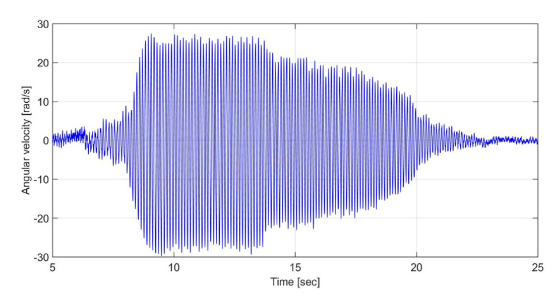
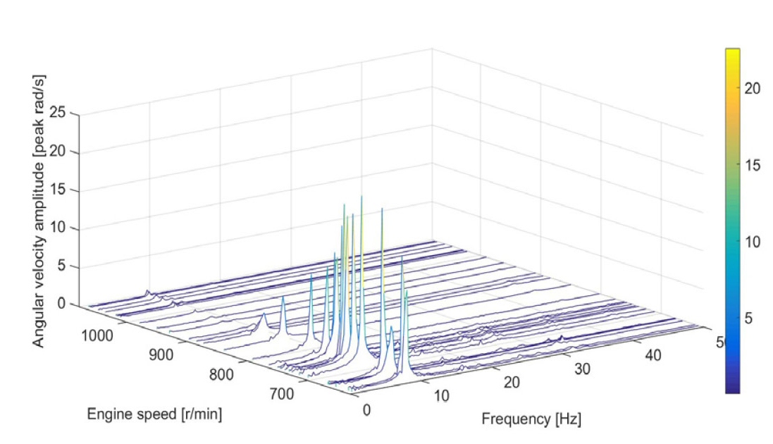
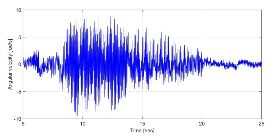
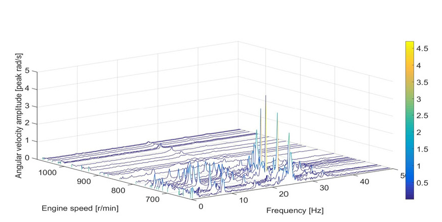
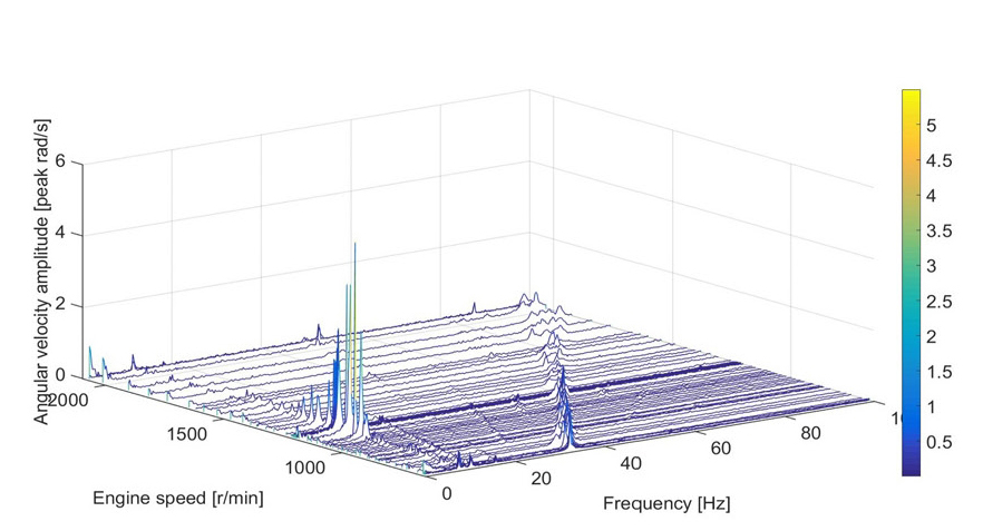
당시 수차에 거쳐 종합적인 진동을 측정하였으나 원인을 확인할 수 없었으며 초기 원인 규명에 실패하였다(1). 다만 선박을 운항하는 동안 불규칙하게 한 순간에 이상 소음과 함께 탄성커플링이 손상되는 사고를 직접 목격하였으며 이때까지도 자려 비틀림진동이라고 확인할 수가 없었다. 또한 추진축계를 엔진 기진력을 중심으로 비틀림진동 해석을 수행하였지만 과잉된 비틀림진동을 확인할 수가 없었다(2). 그 후 다음 시리즈 선박이 건조될 때까지 많은 시간이 경과되었다. 이 선박의 진동과 서로 비교하기 위하여 당시의 방대한 측정 자료를 자체 S/W를 이용(3) 후처리하는 과정 중 단 한 곳에서 자려 비틀림진동을 관찰할 수 있었으며 그 결과를 Figs. 7 ~ 10에 보인다. Figs. 7 ~ 8을 보면 약 20초 동안 엔진의 회전 속도가 600 r/min부터 자려 비틀림진동이 성장하다가 800 r/min가 되면 자려 비틀림진동이 사라진다. 이 실험에서 아주 짧은 시간에 엔진 회전수를 올렸기 때문에 탄성커플링이 파손이 되지 않아 자려진동의 발생과(4,5) 소멸되는 정상적인 신호를 얻을 수 있었다. 여기서 비틀림진동 해석과 측정 결과를 확인하면 1절 고유진동수 보다 약간 낮은 8.7 Hz의 자려진동이 발생하였다. 또한 엔진의 회전수를 2200 r/min부터 천천히 낮출 경우 Fig. 11과 같이 1200 r/min ~ 1000 r/min 사이에서 0.5차 9 ~ 10 Hz의 공진을 확인할 수 있다. 이는 엔진의 실린더 내 착화실패가 일어나지 않음에도 카단축의 속도변동 및 마찰과 고무의 비선형 특성에 의해서 진동이 성장하였다. 이때 진동각속도 변동은 7 rad/s ~ 8 rad/s로 주파수가 낮기 때문에 각 진폭으로 변환하면 대단히 크다.

Natural frequencies of torsional vibration and engine structural vibration of transverse direction(Unit: cycle per min)
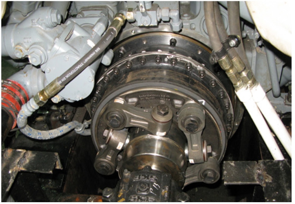
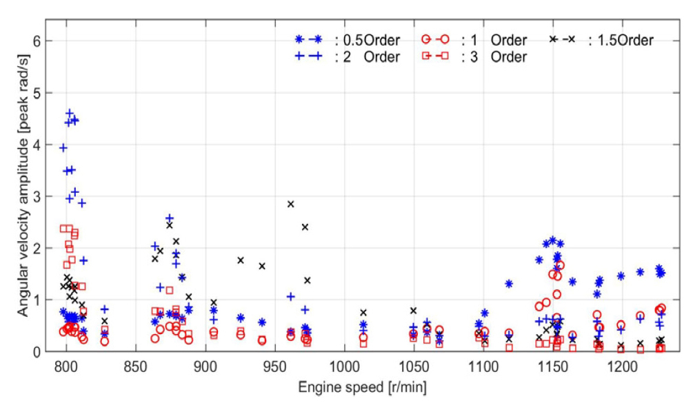
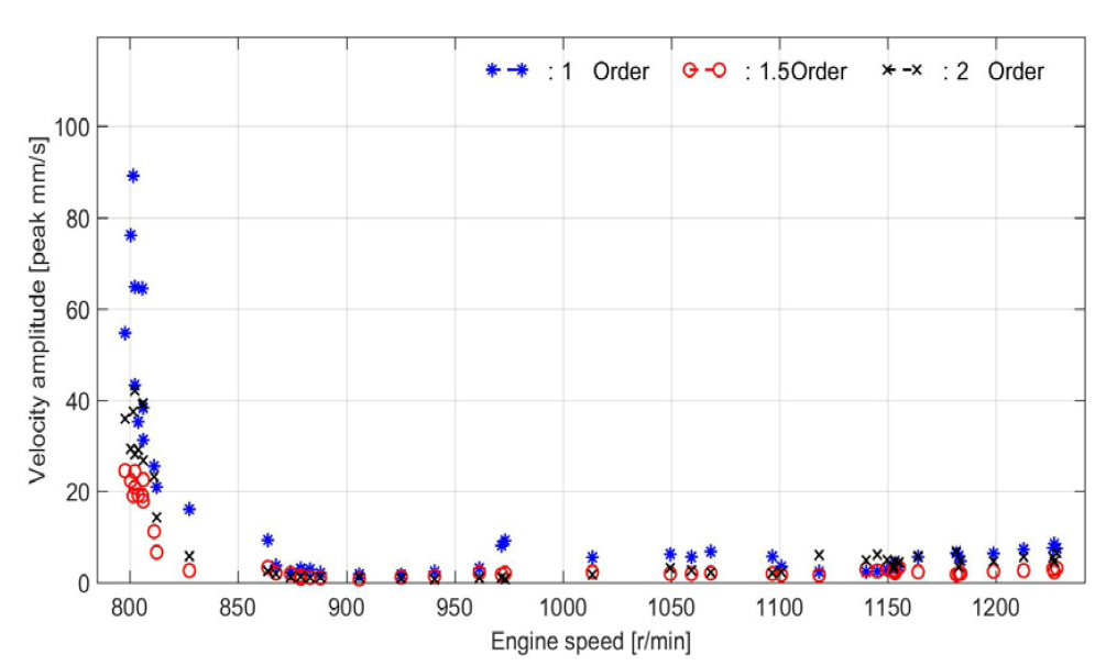
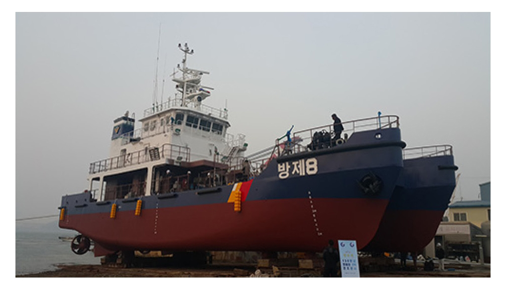
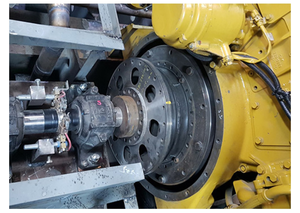
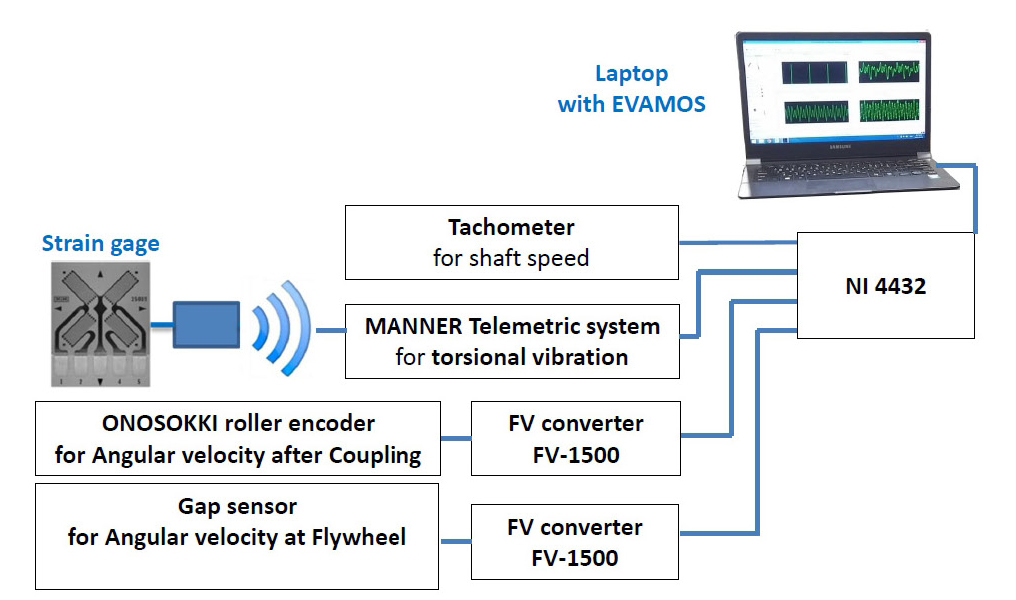
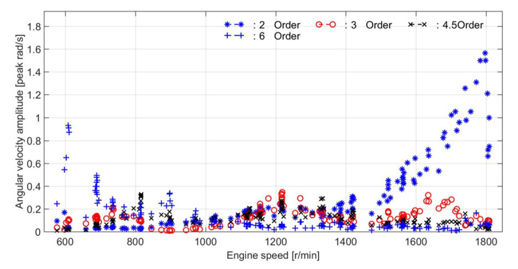
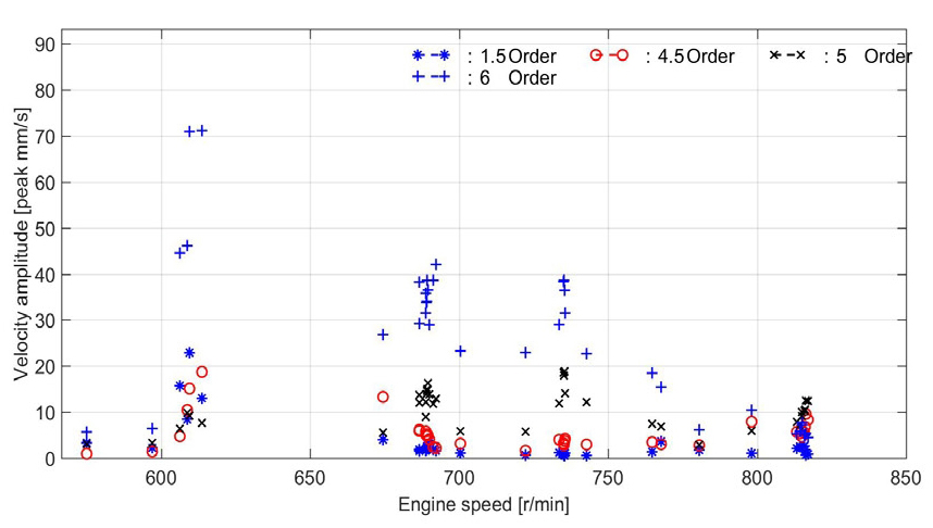
탄성커플링의 파손사고를 방지하여 선박을 정상적으로 인도하기 위하여 기존 탄성커플링과 거의 유사한 비틀림 강성을 갖고 3축방향의 변위를 흡수할 수 있도록 Fig. 12와 같은 플랙시블 링크를 갖는 탄성 커플링 B(CentaxⓇ CX-64-LFS2-50-14)를 재설계하여 기존 탄성커플링 A와 서로 교체하였다. 다행히 자려진동이 발생하지 않았으나 엔진회전수가 낮을 경우 Fig. 13과 같이 1, 2차 비틀림진동이 상당히 증가한다. Fig. 14는 플랙시블 링크가 있는 축 방향에서 레이저 진동측정기로 측정한 커플링의 구조진동 결과로 800 r/min보다 낮은 회전수에서 구조진동이 심해 공회전 속도를 830 r/min까지 증가시켜야만 하였다. 이후 동형선에 추진시스템은 동일하고 엔진은 진동특성이 유사한 동일한 실린더 수 및 출력을 갖는 엔진(Caterpillar C32, 735 kW × 1800 r/min)을 선정하였다. Fig. 15는 건조된 동형 선박의 사진이며 여기서 시스템을 개선하기 위하여 탄성커플링 B를 보완한 탄성커플링 C(Stromag TRI-R TEF 42.3 W-2R 18 inch)로 Fig. 16에 보인다. 그림에서 좌측 출력 측은 스틸 디스크는 중량을 줄이기 위해 홀을 갖는 비교적 얇은 판이다. 따라서 탄성커플링 A, B와 거의 유사한 비틀림 강성을 갖고 3축 방향으로 충분한 유연성을 갖도록 하여 축 측에서 탄성커플링의 중량만을 줄였다. Fig. 17은 진동 측정을 위한 계통도로 추가로 카단축에서 비틀림진동 응력을 측정하였다. Fig. 18은 탄성커플링 C의 엔진 측에서 측정한 각속도 변동으로 회전수가 낮은 600 r/min 근처에서는 6차가 주진동이며 엔진회전수가 높은 1800 r/min 근처에서는 2차가 주성분이다. Fig. 19는 카단축의 비틀림진동 응력으로 Fig. 18과 비슷한 진동양상을 보이나 1800 r/min 근처에서 1차성분이 증가하지만 우려할만한 수준은 아니다. 또한 탄성커플링 C의 동적 거동을 확인하기 위하여 별도로 레이저 진동계를 이용한 측정된 속도변동을 Fig. 20에 보인다. 여기서 850 r/min 이하에서는 진동신호가 정상적으로 비틀림진동의 영향에 의한 6차성분이 나타나지만 우려되는 수준은 아니다. 비틀림진동과 탄성커플링의 동적거동을 확인한 결과 Z-드라이브 프로펠러를 갖는 이 유형의 150톤급 방제선은 탄성커플링 C가 적합하였다.
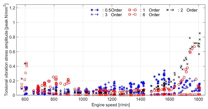
Order analysis of torsional vibration stress of Cardan shaft with flexible coupling C during acceleration
4. 결 론
이 연구는 Z-드라이브 프로펠러를 갖는 150톤급 방제선을 중심으로 추진축계의 동적 거동을 확인하여 안정성을 평가하였으며 이를 정리 요약하면 다음과 같다.
(1) 선박용 추진시스템에서 경험하기 힘든 자려 비틀림진동을 확인하였으며 진동의 성장속도가 빨라 아주 짧은 시간(약 30초 이내)에 파손사고로 이어짐을 육안으로 확인하였다. 이 자려 비틀림진동이 일어나는 탄성커플링은 중간축에 3축 방향으로 유연성이 작은 종류였고 비교적 동력의 전달시 마찰손실이 예상되는 카단축이 두 곳이고 이는 기진력으로 작용할 수 있는 추진시스템이었다.
(2) 자려 비틀림진동을 피하기 위하여 플랙시블 링크와 함께 중간축에 3축 방향으로 유연성이 큰 것으로 대체하였으나 엔진의 운전범위가 낮은 회전수 영역에서 커플링의 플렉시블 링크 자체중량으로 인하여 구조진동이 심하여 공회전 속도를 높게 조정하였다. 최종적으로 탄성커플링이 중간축에서 3축 방향으로 유연성이 큰 것으로 대체하고 탄성커플링의 출력 측의 중량을 줄인 결과 전반적으로 비틀림진동 및 축의 횡진동이 감소하여 시스템의 안정성을 얻을 수 있었다.
(3) 선박용 추진시스템은 통합적인 설계 및 검토가 필요함에도 발주자 측에서 주기관의 디젤엔진과 추진시스템이 분리 발주됨에 따라 전체적인 통합설계가 이루지지 않고 조선소와도 책임도 불분명하였으며 전체적인 진동 해결에 어려움이 있었다.
Acknowledgments
# A part of this paper was presented at the KSNVE 2018 Annual Spring Conference
이 연구는 산업통상자원부 소관 산업융합기반구축사업의 “중소형 선박엔진 및 관련기자재 공인시험인증센터 구축” 사업의 지원을 받아 수행되었습니다.
References
- Dynamics Laboratory of Mokpo Maritime University, (2009), Torsional and Engine Structural Vibration Measurement for Korea Coast Guard Bang-je No. 5, Document No. MDL-09051-r1.
- Vulkan Couplings and Gears, (2009), Torsional Vibration Analysis, Document No. 20_09_1.028.
-
Lee, D. C., Joo, K. S., Nam, T. K., Kim, E. S., and Kim, S. H., (2009), Development of Engine Vibration Analysis and Monitoring System (EVAMOS) for Marine Vessels, Transactions of the Korea Society for Noise and Vibration Engineering, 19(2), p155-162.
[https://doi.org/10.5050/KSNVN.2009.19.2.155]

- Lee, D. C., and Yu, J. D., (2003), Transient and Unstable Torsional Vibrations on a 4-Stroke Marine Diesel Engine, Proceeding of ICES03 2003 Spring Technical Conference of The ASME Internal Combustion Engine Division, Salzburg, Austria, May, p11-14.
-
Lee, D. C., and Barro, R. D., (2014), Self Excited Vibration in a Specialised Electric Propulsion System, MTZ Industrial, 4(2), p54-59.
[https://doi.org/10.1007/s40353-014-0140-y]


Donchool Lee received his Dr. Eng. from Mechanical Engineering department at Korea Maritime University in 1995. He worked at Hyundai Heavy Industries from 1983 to 1999. He is now a professor of Mokpo National Maritime University.

Gahyang Lee received her B. Eng. from Mokpo Maritime University in 2018. She is now working Ship Repair Supporting Center. Also she is studying Master course at Dynamics Lab. of Mokpo maritime university.
Quang Dao Vuong received his B. Eng. from Vietnam Maritime University and his M. Eng. from Mokpo National Maritime University. Now he is studying Doctor course at Dynamics Lab. of Mokpo National Maritime University.
