Frequency Equation of a Curved Beam using the Phase-closure Principle
© The Korean Society for Noise and Vibration Engineering
Abstract
This paper presents a simplified frequency equation that predicts the modal frequencies of a curved beam. In particular, the simplified frequency equation is derived for a frequency range within which one pair of propagating wave motions and two pairs of evanescent wave motions exist on the curved beam. All incident evanescent wave motions are assumed to be negligible at both ends of the beam. The phase-closure principle is applied to a curved beam with varying support conditions. First, the wave reflection coefficients for the curved beam are calculated, after which the phases of the reflection coefficients are applied using the phase-closure principle to derive the frequency equation. Then, the Newton-Raphson method is employed to compute the modal frequencies from the frequency equation. The proposed frequency equation is validated with numerical results for varying support conditions and span angles.
초록
이 논문은 곡선보의 모드 진동수를 예측하기 위해 단순화된 진동수 방정식을 제시한다. 특히, 한쌍의 전달 파동과 두쌍의 소멸 파동이 존재하는 곡선보의 진동수 범위에서 단순화된 진동수 방정식을 유도한다. 보의 양쪽 지점으로 입사되는 소멸 파동은 무시할 수 있다고 가정한다. 위상폐합원리를 다양한 지점 조건을 가지는 곡선보에 적용한다. 곡선보에서 파 반사 계수를 먼저 계산한 후 파 반사에 의한 위상변화를 위상폐합원리에 적용하여 진동수 방정식을 유도한다. 진동수 방정식으로부터 모드 진동수를 계산하기 위해 뉴턴-랩슨법을 적용한다. 제안된 주파수 방정식은 다양한 지지 조건 및 스팬 각도에 대한 수치 해석 결과로 검증한다.
Keywords:
Frequency Equation, Curved Beam, Phase-closure Principle, Dispersion Curve, Numerical Analysis, Newton-Raphson Method키워드:
진동수 방정식, 곡선보, 위상폐합원리, 분산곡선, 수치해석, 뉴턴-랩슨법1. Introduction
Vibration of curved beams has been the subject of numerous studies(1~4). Curved beams are commonly used in engineering structures such as aircraft structures, bridges, and modern electric machine parts(5~6).
Various methods are applied to study the dynamics of curved beam structures. The Rayleigh-Ritz method was used to formulate a frequency equation to derive the lowest natural frequencies of circular arcs with varying boundary conditions(7). Chidamparam and Leissa utilized the Galerkin method to obtain exact natural frequencies for extensional and inextensional loaded circular arches(8). The transfer matrix method was employed to investigate in-plane and out-of-plane frequencies of plane curved beams while accounting for shear deformation, rotatory inertia and extension of neutral axis(9). Issa et al.(10) applied the dynamics stiffness method to the effects of shear deformation and rotatory inertia on extensional free vibrations to determine natural frequencies of continuous curved beams. The widely used method, the finite element method (FEM), was employed to study the static and free vibration of linear beam elements for curved beams (11). Most of the mentioned methods become extremely burdensome when large number of spans are used(12). The FEM is also computationally expensive when a refined mesh is required for predicting the high-frequency modal frequency which is sensitive to an incipient crack on the beam(13).
The wave approach is another method employed to analyze curved beams. It is a concise and systematic approach used to analyze structures since it easily allows efficient variation of the geometry and size of complex structures. Studies have applied the wave approach to predict the modal frequencies of curved beams(14~16). Natural frequencies of curved beams can be obtained while using a common wave technique of formulating propagation, reflection and transmission characteristics of waves.
This wave technique is based on a principle known as the phase-closure principle(17). The phase-closure principle is also called the wave-train closure principle(18). The phase-closure principle is one where natural frequencies occur when the total phase change of a complete circuit of a wave propagating around a system is an integer multiple of 2π.
Mead(17) applied the phase-closure principle to formulate an exact frequency equation for a single span fixed beam while using propagating and evanescent waves. Tang et al.(19) used a simplified frequency equation to calculate the natural frequencies of a uniform rod and beam with nonlinear stiffness boundaries. The phase of the reflection coefficients at each boundary were applied with the phase-closure principle to obtain the natural frequencies of the system.
This study aims to formulate a simplified frequency equation for a curved beam using the phase-closure principle to predict high-frequency modal frequencies. In particular, the simplified frequency equation is derived for a frequency range within which one pair of propagating wave motions and two pairs of evanescent wave motions exist on the curved beam.
The reflection coefficients at varying support conditions are calculated. The phases are obtained from the reflection coefficients. Then, the phases of each support condition are applied with the phase-closure principle to determine the modal frequencies of a single span curved beam. The modal frequencies for the beam calculated from the proposed frequency equation are then presented and compared with those from the matrix determinant method. The advantages of the proposed method are discussed as well.
2. Spectral Solutions of a Curved Beam
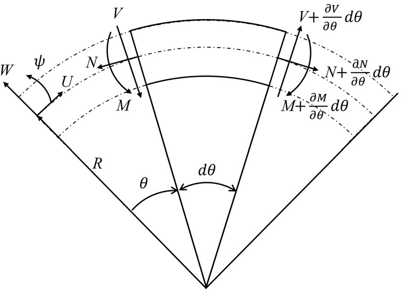
The governing equations of motion are considered from Fig. 1 where N, V and M are axial force, shear force and bending moment, respectively(20). Note that effects of rotary inertia, shear deformations and damping are neglected.
The normalized equations of motion in Eq. (1) are modified from non-dimensional variables and parameters given as
| (1a) |
| (1b) |
| (1c) |
where u, w and t are the non-dimensional tangential, radial displacements and time variable respectively. R is the constant radius of curvature for the given range of angle θ, T0 is the characteristic time, ρ is the mass density, A is the cross-sectional area, E is Young’s modulus, I is second moment of inertia. Furthermore, curvature parameter k is defined as the ratio of the radius of gyration of the cross-section to the radius of curvature R.
Time harmonic solutions were assumed to solve the governing equations which are provided as
| (2a) |
| (2b) |
where γ and ω are non-dimensional wavenumber normalized by 1/R and non-dimensional frequency normalized by 1/T0, respectively.
The dispersion equation of the wave number γ obtained from the determinant of matrix of harmonic solutions is provided as
| (3) |
Figure 2 illustrates the dispersion curves obtained by solving Eq. (3) for both extentional and inextensional curved beams(20). Four distinct wave motions which are depicted as from Case I to IV can be observed in Fig. 2. Among these four cases of wave motions, this study focuses on Case III in which one pair of propagating wave motions and two pairs of evanescent wave motions exist for both extensional and inextensional curved beams. The spectral solution for Case III can be expressed as follows:
| (4) |
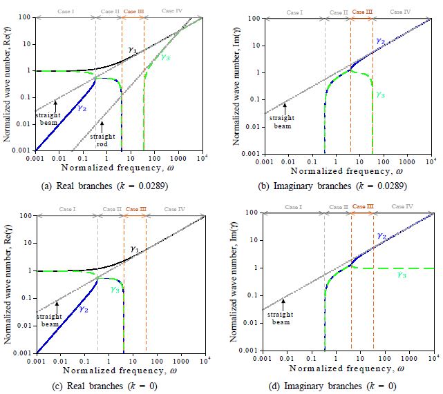
Dispersion curves of a curved beam for extentioned case (k = 0.0289) and for inextensional case (k = 0), the dispersion curves of straight beam and rod are presented as well for comparison purposes
where γ1 is a positive real root while γ2 and γ3 are two negative roots obtained from Eq. (3).
The phase-closure principle is easily applied with Case III of wave motion since one pair of propagating wave motions is used to predict the natural frequencies of structure. The range of frequency for Case III wave motion is 4.164 < ω < ωc = 34.641.
3. Simplified Frequency Equation from the Phase-closure Principle
3.1 Reflection coefficient
The spectral solutions of normalized radial and tangential displacement are expressed as follows
| (5a) |
| (5b) |
where
| (5c) |
| (5d) |
The displacement and moment boundary conditions at a hinged support (θ=0)are expressed as
| (6a) |
| (6b) |
| (6c) |
Substituting Eqs. (5) into Eqs. (6) results in:
| (7a) |
| (7b) |
| (7c) |
where
and . Eqs. (7a) ~ (7c) are simplified as follows by assuming that all incident evanescent wave motions associated with are egligible in and .
| (8a) |
| (8b) |
| (8c) |
Adding α2×Eq. (8a) to Eq. (8b) results in
| (9) |
Adding -β2×Eq. (8a) to Eq. (8c) produces
| (10) |
Adding (β2-β3)×Eq. (9) to (α2-α3)×Eq. (10) yields
| (11) |
Using Eq. (11), reflection coefficient r from incident propagating wave motion to reflected propagating wave motion can be expressed as follows
| (12) |
(βi-βj) in Eq. (12) can be written as
| (13) |
where qi = αi + iγi.
Substituting Eq. (13) into Eq. (12) results in
| (14) |
The same procedure of obtaining the reflection coefficient is applied for fixed and free support conditions as respectively (elaborated in appendix A),
| (15) |
| (16) |
where pi = αi + (i/γi).
3.2 Frequency equation
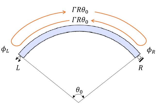
The phase-closure formula is applied to the curved beam shown in Fig. 3. The equations are derived as follows.
| (17) |
where dΓ, ϕL and ϕR are the phase shift of the propagating wave along the infinitesimal segment of the curved beam, the phase shifts due to wave reflections at the right and left end of the beam respectively while c is an arbitrary integer. Assuming a constant curvature along the whole length of the curved beam, Eq. (17) can be written as:
| (18) |
where θ0 is the span angle of the curved beam, respectively. Substituting Γ=γ/R into Eq. (18) results in:
| (19) |
Note that the ϕL and ϕR are determined by the phase of a reflection coefficient which is expressed in Eqs. (14) ~ (16) depending on the support types of the curved beam.
3.3. Numerical solutions of the frequency equation using Newton-Raphson (N-R) method
The numerical solutions of Eq. (19) are obtained using the Newton-Raphson method because the frequency equation is nonlinear with respect to non-dimensional angular frequency ω. The frequency equation Eq. (19) is rewritten as:
| (20) |
The modal angular frequency ω satisfying Eq. (20) is solved iteratively by linearizing Eq. (20) with respect to ω:
| (21) |
where j denotes the number of the N-R iteration while yj and dyj/dω represent y|ω=ωj and dy/dω|ω=ωj, respectively. The solution increment Δω is expressed as follows by using Eq. (21).
| (22) |
The modal frequency is updated by adding the solution increment from Eq. (22):
| (23) |
The N-R iteration is repeated by using Eqs. (21) ~ (23) until the following termination criterion is satisfied:
| (24) |
where ϵ is termination tolerance (e.g. ϵ = 10-7)
The first order derivative y with respect to ω is expressed as:
| (25) |
where γ1 is a positive real root of the dispersion equation of a curved beam for case III region expressed as:
| (26) |
dγ1/dω in Eq. (25) is obtained by differentiating Eq. (26) with respect to ω:
| (27) |
dy/dγ1 in Eq. (25) is expressed as follows by differentiating Eq. (20) with respect to γ1:
| (28) |
where ′ denotes the differential operator with respect to r1.
Assuming that both support conditions at the left and right ends of the beam are identical, ϕL and ϕR in Eq. (20) are expressed as follows using the reflection coefficient r:
| (29) |
where r is calculated by using Eqs. (14) ~ (16) depending on the types of the support conditions.
Decomposing r into a real part Re(r) and an imaginary part Im(r), Eq. (29) is rewritten as:
| (30) |
Differentiating Eq. (30) with respect to γ1 results in
| (31) |
Note that Im(r)′ and Re(r)′ in Eq. (31) can be obtained through differentiating the reflection coefficient r with respect to γ1.
| (32) |
where Re(r)′ = Re(r′) and Im(r)′ = Im(r′).
The first order derivative r′ is obtained through differentiating Eqs. (14) ~ (16) depending on the type of the support condition. The detailed procedure to derive r′ is provided in Appendix B.
4. Results and Discussions
The numerical solutions of the proposed frequency described in Section 3 are validated for both extensional and inextentional curved beams with varying support conditions and span angles. Table 1 provides the non-dimensional natural frequencies of a curved beam with span angles 90° and 180° for three support conditions. The results in Table 1 were compared with those obtained by the matrix determinant method which is described in appendix C.
As shown in Table 1, the frequency equation of this study reasonably predicted the natural frequencies of the curved beam. The relative error between predictions of the current study and the determinant matrix method is considerably small. For the extensional case, the error tends to fluctuate with increase in the mode number as compared to the inextensional case. The error in the inextensional case decreases as the mode number increases.
The respective comparison results for span angle 90° are provided in Fig. 4. The circle and the square represent the natural frequencies from the matrix determinant method and the proposed method in Table 1, respectively. The red and blue lines depict real and imaginary values of C(ω) in Eq. (C7) with respect to while the black line depict the equation residual of y in Eq. (20) with respect to ω.
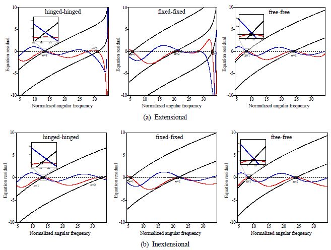
Comparison of the natural frequencies between matrix determinant method and the proposed method for a curved beam with span angle 90° (circle: roots of C(ω)in Eq. (C7), square: roots of in Eq. (20), red line: Re(C(ω)), blue line: Im(C(ω)), black line: y in Eq. (20))
It should be noted that substituting the roots of the proposed frequency equation in Eq. (20) into C(ω)results in Re(C(ω)) = 0 and Im(C(ω)) ≠ 0 for all cases. This implies that the proposed frequency equation in which incident evanescent wave motions at both supports are neglected produces the roots satisfying Re(C(ω)) = 0 only. Therefore, the discrepancy of the natural frequencies between the proposed frequency equation and the matrix determinant method depends on the distance between the roots of Re(C(ω)) = 0 with Im(C(ω)) ≠ 0 and those of Re(C(ω)) = 0 with Im(C(ω)) = 0. For the extensional curved beam, the discrepancy becomes significant as approaches either the low cut-off frequency (i.e. 4.164) dividing case II and III regions or the high cut-off frequency (i.e. 34.641) dividing case III and IV regions in Figs. 2(a) ~ (b) due the appearance of incident evanescent wave motions. For the inextensional curved beam, the discrepancy becomes significant as approaches the low cut-off frequency dividing case II and III regions because there is no case IV region as shown in Figs. 2(c) ~ (d). The fictitious natural frequency (n=1) appears for both extensional and inextensional fixed-fixed curved beams due to the incident evanescent wave motions near the low-cut off frequency. The relatively large errors in the second and the third natural frequencies of the extensional hinged-hinged and fixed-fixed curved beams can be attributed to the incident evanescent wave motions near the high cut-off frequency. Note that the errors in the natural frequencies of the inextensional curved beams decrease as increases regardless of the support conditions. This indicates that the incident evanescent wave motions vanish as the frequency increases in case III region.
Figure 5 presents the respective comparison results for span angle 180°. The meanings of all symbols and lines are identical to those used in Fig. 4. As the span angle is doubled, the errors in the first natural frequency significantly decreases compared to those in Fig. 4 for both extensional and inextensional curved beams regardless of the support conditions. For higher natural frequencies near the high cut-off frequency, the error decreases significantly for the extensional curved beam compared to those in Fig. 4. In case of inextensional curved beams, the proposed frequency equation produces practically identical results from the matrix determinant method as increases.
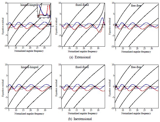
Comparison of the natural frequencies between matrix determinant method and the proposed method for a curved beam with span angle 180° (circle: roots of C(ω)in Eq. (C7), square: roots of in Eq. (20), red line: Re(C(ω)), blue line: Im(C(ω)), black line: y in Eq. (20))
The advantages of the proposed method over the matrix determinant method can be described in two aspects. First, y in the frequency equation [Eq. (20)] is a monotonically increasing function with respect to per mode number n which results in a single root per each as shown in Fig. 4 and Fig. 5. Second, y in Eq. (20) is a concave function in the vicinity of the root in most cases except that it exists near the high cut-off frequency. Therefore, the N-R method produces the converged solution within a few iterations as long as the initial guess is set near the low cut-off frequency (e.g. 5).
C(ω) in the frequency equation [Eq. (C7)] is a transcendental function with respect to in which multiple roots exist. In this case, the convergence of the N-R method highly depends on the initial guess which should be decided by trial and error. Therefore, searching for all roots in C(ω) may become a very laborious task.
This study has some limitations. Only propagating wave components were used and the incident evanescent wave motions were neglected. Therefore, the proposed frequency equation only provides approximate results for the natural frequencies. It also should be noted that the proposed method is complementary to the matrix determinant method because the proposed frequency equation can provide the reliable initial guess when the N-R method is adopted in the matrix determinant method.
5. Conclusions
This paper has proposed a simple closed-form frequency equation to predict the modal frequencies of a curved beam considering the phase-closure principle. The frequency equation is derived for a frequency range within which one pair of propagating wave motions and two pairs of evanescent wave motions exist. The reflection coefficients at each boundary were derived from which phases of reflection were obtained and applied to the phase-closure principle to determine the high-frequency modal frequencies of a curved beam.
The proposed frequency equation was validated for both extensional and inextentional curved beams with span angles 90° and 180° for three support conditions. The numerical solutions calculated from the proposed equation were comparable with those from the matrix determinant method. The interesting point is that every solution from the proposed frequency equation always makes only the real part of the frequency equation from the matrix determinant method zero while the corresponding imaginary part nonzero. Overall, the discrepancy of the natural frequencies between the proposed frequency equation and the matrix determinant method is attributed to the incident evanescent wave motions near the low and high cut-off frequencies of the case III region.
The relative error between the numerical solutions of the proposed frequency equation and the matrix determinant method decreased as the mode number increased especially for inextensional curved beams. Furthermore, the proposed frequency equation produces the converged solution within a few iterations as long as the initial guess is set near the low cut-off frequency. The formulated frequency equation is simple, easy and more straight forward in obtaining approximate natural frequencies of a curved beam.
The proposed method is complementary to the matrix determinant method because the proposed frequency equation can provide the reliable initial guess when the N-R method is adopted in the matrix determinant method.
Acknowledgments
This research was conducted with the support of the “National R&D Project for Smart Construction Technology (21SMIP-A156444-02)” funded by the Korea Agency for Infrastructure Technology Advancement under the Ministry of Land, Infrastructure and Transport and managed by the Korea Expressway Corporation. The first author would like to acknowledge the Korean Government Scholarship Program (KGSP) for her Graduate degree during her stay at Dong-A University from 2019 to 2021.
References
-
Mau, S. T. and Williams, A. N., 1988, Green’s Function Solution for Arch Vibration, Journal of Engineering Mechanics, Vol. 114, No. 7, pp. 1259~1264.
[https://doi.org/10.1061/(ASCE)0733-9399(1988)114:7(1259)]

-
Chidamparam, P. and Leissa, A. W., 1993, Vibrations of Planar Curved Beams, Rings, and Arches, Applied Mechanics Reviews, Vol. 46, No. 9, pp. 467~483.
[https://doi.org/10.1115/1.3120374]

-
Yang, F., Sedaghati, R. and Esmailzadeh, E., 2018, Free In-plane Vibration of Curved Beam Structures: A Tutorial and the State of the Art, Journal of Vibration and Control, Vol. 24, No. 12, pp. 2400~2417.
[https://doi.org/10.1177/1077546317728148]

-
Tüfekçi, E. and Arpaci, A., 1998, Exact Solution of In-plane Vibrations of Circular Arches with Account Taken of Axial Extension, Transverse Shear and Rotatory Inertia Effects, Journal of Sound and Vibration, Vol. 209, No. 5, pp. 845~856.
[https://doi.org/10.1006/jsvi.1997.1290]

-
Tanna, R. P. and Lim, T. C., 2004, Modal Frequency Deviations in Estimating Ring Gear Modes using Smooth Ring Solutions, Journal of Sound and Vibration, Vol. 269, No. 3-5, pp. 1099~1110.
[https://doi.org/10.1016/S0022-460X(03)00407-3]

-
Erdelyi, E. and Horvay, G., 1957, Vibration Modes of Stators of Induction Motors, Journal of Applied Mechanics, Vol. 24, No. 1, pp. 39~45.
[https://doi.org/10.1115/1.4011441]

-
Den Hartog, J. P., 1928, XL. The Lowest Natural Frequency of Circular Arcs, The London, Edinburgh, and Dublin Philosophical Magazine and Journal of Science, Vol. 5, No. 28, pp. 400~408.
[https://doi.org/10.1080/14786440208564480]

-
Chidamparam, P. and Leissa, A. W., 1995, Influence of Centerline Extensibility on the In-plane Free Vibrations of Loaded Circular Arches, Journal of Sound and Vibration, Vol. 183, No. 5, pp. 779~795.
[https://doi.org/10.1006/jsvi.1995.0286]

-
Bickford, W. B. and Strom, B. T., 1975, Vibration of Plane Curved Beams, Journal of Sound and Vibration, Vol. 39, No. 2, pp. 135~146.
[https://doi.org/10.1016/S0022-460X(75)80213-6]

-
Issa, M. S., Wang, T. M. and Hsiao, B. T., 1987, Extensional Vibrations of Continuous Circular Curved Beams with Rotary Inertia and Shear Deformation, I: Free Vibration, Journal of Sound and Vibration, Vol. 114, No. 2, pp. 297~308.
[https://doi.org/10.1016/S0022-460X(87)80155-4]

-
Krishnan, A., and Suresh, Y. J., 1998, A Simple Cubic Linear Element for Static and Free Vibration Analyses of Curved Beams, Computers & Structures, Vol. 68, No. 5, pp. 473~489.
[https://doi.org/10.1016/S0045-7949(98)00091-1]

-
Chen, S. S., 1973, In-plane Vibration of Continuous Curved Beams, Nuclear Engineering and Design, Vol. 25, No. 3, pp. 413~431.
[https://doi.org/10.1016/0029-5493(73)90037-X]

- Jeong, C. H. and Ih, J. G., 2001, High Frequency Vibration Analysis of Single Curved Beam using the Ray Tracing Method, Proceeding of the KSNVE Annual Autumn Conference, pp. 90~95.
-
Mallik, A. K. and Mead, D. J., 1977, Free Vibration of Thin Circular Rings on Periodic Radial Supports, Journal of Sound and Vibration, Vol. 54, No. 1, pp. 13~27.
[https://doi.org/10.1016/0022-460X(77)90402-3]

-
Kang, B. and Riedel, C. H., 2012, Coupling of In-plane Flexural, Tangential, and Shear Wave Modes of a Curved Beam, Journal of Vibration and Acoustics, Vol. 134, No. 1., pp. 1~13.
[https://doi.org/10.1115/1.4004676]

-
Xiuchang, H., Hongxing, H., Yu, W. and Zhipeng, D., 2013, Research on Wave Mode Conversion of Curved Beam Structures by the Wave Approach, Journal of Vibration and Acoustics, Vol. 135, No. 3., pp. 1~16.
[https://doi.org/10.1115/1.4023817]

-
Mead, D. J., 1994, Waves and Modes in Finite Beams: Application of the Phase-closure Principle, Journal of Sound and Vibration, Vol. 171, No. 5, pp. 695~702.
[https://doi.org/10.1006/jsvi.1994.1150]

-
Cremer, L., Heckl, M. and Petersson, B. A. T., 2005, Structure-borne Sound: Structural Vibrations and Sound Radiation at Audio Frequencies, 3rd Edition, Springer, Berlin.
[https://doi.org/10.1007/b137728]

-
Tang, B., Brennan, M. J. and Manconi, E., 2018, On the Use of the Phase Closure Principle to Calculate the Natural Frequencies of a Rod or Beam with Nonlinear Boundaries, Journal of Sound and Vibration, Vol. 433, pp. 461~475.
[https://doi.org/10.1016/j.jsv.2018.05.002]

-
Kang, B., Riedel, C. H. and Tan, C. A., 2003, Free vibration analysis of planar curved beams by wave propagation, Journal of sound and vibration, Vol. 260, No. 1, 19~44.
[https://doi.org/10.1016/S0022-460X(02)00898-2]

Appendix
Appendix A
a) Fixed support condition
The displacement and rotational boundary conditions at fixed support (θ = 0) are expressed as
| (A1a) |
| (A1b) |
| (A1c) |
Substituting Eqs. (5) into Eq. (A1) results in:
| (A2a) |
| (A2b) |
| (A2c) |
Equations. (A2a) ~ (A2c) are simplified as follows due to the assumption that all incident evanescent wave motions are negligible:
| (A3a) |
| (A3b) |
| (A3c) |
Adding α2×Eq. (A3a) to Eq. (A3b) results in
| (A4) |
Adding -β2 × Eq. (A3a) to Eq. (A3c) produces
| (A5) |
Adding (β2-β3) × Eq. (A4) to (α2-α3)×Eq. (A5) produces the reflection coefficient γfixed in Eq. (15) through some mathematical manipulation.
b) Free support condition
The displacement and rotational boundary conditions at free support (θ = 0)are expressed as
| (A6a) |
| (A6b) |
| (A6c) |
Substituting Eqs. (5) into Eqs. (A6a) ~ (A6c) results in:
| (A7a) |
| (A7b) |
| (A7c) |
Equations (A7a) ~ (A7c) are simplified as follows due to the assumption that all incident evanescent wave motions are negligible:
| (A8a) |
| (A8b) |
| (A8c) |
Adding Eq. (A8a) to iγ2p2×Eq. (A8b) results in
| (A9) |
Adding β2×Eq. (A8a) to -iγ2p2×Eq. (A8c) produces
| (A10) |
Adding (iγ2p2β3-iγ3p3β2)×Eq. (A9) to ×Eq. (A10) produces the reflection coefficient rfree in Eq. (16) through some mathematical manipulation.
Appendix
Appendix B
The derivative of reflection coefficient with respect to γ1 (r′)can be expressed through the derivatives of rational functions as follows:
| (B1) |
where U and V represent the numerator and the denominator of r which vary depending on the type of support condition as described in Eqs. (14) ~ (16). The derivatives of variables with respect to γ1 needed to calculate Eq. (B1) are listed below:
a) Derivatives of γ2 and γ3 with respect to γ1
| (B2a) |
| (B2b) |
where
and ω′ can be obtained from Eq. (27).
b) Derivatives of α1, α2 and α3 with respect to γ1
| (B3a) |
| (B3b) |
| (B3c) |
c) Derivatives of p1, p2 and p3 with respect to γ1
| (B4a) |
| (B4b) |
| (B4c) |
d) Derivatives of q1, q2 and q3 with respect to γ1
| (B5a) |
| (B5b) |
| (B5c) |
Appendix
Appendix C
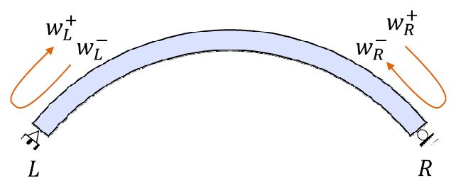
Figure C1 shows a general curved beam structure with boundaries L and R. The incident and reflected wave vector at boundaries are denoted as and .
The relationships of the waves between the boundaries are given as
| (C1a) |
| (C1b) |
| (C1c) |
| (C1d) |
Using Eqs. (C1a) ~ (C1d), the characteristic equation is obtained as follows
| (C2) |
where I denoted the 3×3 identity matrix, rL = rR = r and t are the reflection and transmission matrices expressed as
| (C3) |
| (C4) |
| (C5) |
| (C6) |
For non-trivial solution, the natural frequencies are obtained from the characteristic equation expressed as determinant.
| (C7) |

Nansukusa Mirembe Sarah was a former graduate student at Dept. of Civil Engineering at Dong-A University. The title of her master thesis is “Frequency equation of a curved beam using the phase-closure principle”.

Hyun woo Park recent research interest is analytical, numerical and experimental investigation of high-frequency modal behaviors of a cracked beam from wave propagation perspective. He has demonstrated that the phase closure principle allows for the generic frequency equation of one-dimensional elastic waveguide with multiple incipient cracks as well.
