A Comparative Study on The Rotational Vibration Measurement Using Ordinary Incremental and Absolute Encoders
© The Korean Society for Noise and Vibration Engineering
Abstract
The present study evaluates two procedures for measuring the rotational vibration of a shaft, using an incremental and an absolute encoder, respectively. First, the procedures for rotational vibration measurement using the two encoders are explained. The validity of these procedures is examined through computer simulations, which demonstrate that both procedures are accurate in measuring rotational vibration. Furthermore, the simulation results for both procedures exhibit good correlations in both the time and frequency domains. Finally, the procedures are experimentally verified using a simple test setup with a universal joint to generate rotational vibration. The test results match well with each other and with the theoretical data, confirming that the proposed method is capable of accurately measuring the rotational vibration of rotating machines.
초록
일반적인 증분형 인코더와 절대위치 인코더를 이용하여 회전진동을 특정하는 두 방법을 비교하여 검토하였다. 우선 두 인코더를 이용하여 진동을 측정하는 과정을 설명하였다. 다음으로 컴퓨터 시뮬레이션을 이용하여 두 방법의 타당성을 검토하였으며 결과로 두 방법이 회전진동 측정에 충분한 정확도를 가지고 있으며 두 방법의 결과가 잘 일치하고 있음을 확인하였다. 마지막으로 유니버설 조인트로 연결된 회전축의 회전진동을 두 방법을 적용하여 측정하였다. 두 결과는 서로 잘 일치하며 이론적으로 예측된 값과 잘 부합되는 것을 확인하였다. 결론적으로 상기 두 방법은 회전기계의 회전진동을 정확하게 측정할 수 있음을 확인하였다.
Keywords:
Rotational Vibration, Measurement, Incremental Encoder, Absolute Encoder, Comparative Study키워드:
회전진동, 측정, 증분형 인코더, 절대위치 인코더, 비교 연구1. Introduction
Rotational or torsional vibration which are commonly generated in mechanical or electric system often deteriorate system performances and decreases system endurance limits given large amplitude(1~6). So, the measurement of rotational or torsional vibration is very important for the system inspection and maintenance. Various methods to measure torsional and rotational vibration have been studied and implemented. These methods include angular accelerometer method(7), laser interferometer(8), video images analysis(9) and encoder method(10~12).
Recently encoders are being widely used due to simple application relatively low cost etc. Two types of encoders, incremental encoder and absolute encoder, are being used in the real applications. In the incremental encoder, a pulse will be generated for the specific amount of rotation of the shaft. On the other hand, the absolute encoder gives voltage output proportional to the rotation angle of the shaft.
Application of incremental encoder for the measurement of rotational or torsional vibration has been studied for a long time and several commercial products have been introduced also. Negrea et al. made analytical comparison of the various methods to reduce or compensate the errors in the measurement of rotational vibration using incremental encoders(11). Nam et al. proposed a correction process for the rotational vibration measurement system using incremental encoders(13). The studies on the application of absolute encoders for the measurement of rotational or torsional vibration has not been sufficiently studied thus far. Recently Lee studied the measurement of rotational vibration with ordinary absolute encoders showing that the method has sufficient accuracy in the measurement of rotational vibration(14).
In this study the measurement of rotational vibration with two types of encoders will be comparatively investigated. The measurement processes of rotational displacement and velocity using individual encoders are explained in Sections 2 and 3. Also, in Section 4, the numerical validation using computer software and experimental verifications using the simple test setup with a universal joint for the two processes are provided. Finally, the conclusions of this study are given in Section 5.
2. Measuring Shaft Rotation with Encoders
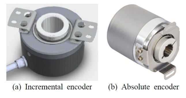
As stated in the previous section, two types of encoders are frequently used for the measurement of the rotational displacement. Fig. 1(a) and Fig. 1(b) shows some examples of ordinary encoders.
Each type of encoder has its own specific mechanism for the measurement of rotational displacement. These mechanisms will be explained in this section and will be used to develop the processes for the rotational vibration measurement of two types of encoders.
2.1 Rotational Displacement Measurement Using an Incremental Encoder
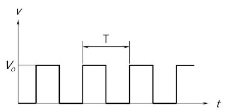
An ordinary incremental encoder that generates a square pulse per pre-determined rotation angle of the shaft is used in this study. As explained above, the incremental encoder generates a specific number (pulses per revolution: PPR) of pulses per revolution. In case of no rotational vibration or disturbance, the output of the encoder would be in the shape of that in Fig. 2.
If the numbers of pulses from the encoder is N, the rotation angle (θ) of the shaft can be calculated with Eq. (1) by dividing 2πN with PPR.
| (1) |
2.2 Rotational Displacement Measurement Using an Absolute Encoder
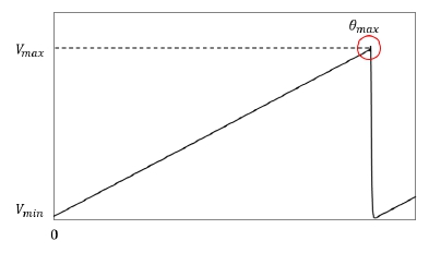
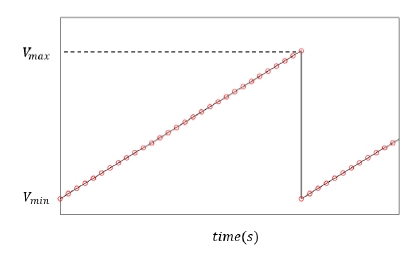
The absolute encoder generates the voltage output proportional to the rotational angle of the shaft from a specific reference point. An example voltage output from the absolute encoder is explained in Fig. 3 where the output voltage increases linearly from Vmin to Vmax according to the rotation angle in the range from 0 to θmax. In this plot the disturbances and rotational vibration of the shaft are assumed to be negligible. And the rotation angle of the shaft at a specific time slot can be obtained by measuring the output voltage at the given instant. Also, the number of rotations of the shaft can be calculated with the number of triangular pulses in the given time interval.
3. Measurement of Rotational Vibration Using Encoders
In this section, the processes for the rotational vibration measurement of the two types of encoders based on their rotational displacement measurement mechanisms are explained. The processes are developed based on the characteristics of the output voltage of each type of encoder
3.1 Rotational Vibration Measurement Using Incremental Encoder
In this section, the process for the rotational vibration measurement of the incremental encoder is provided. In case of the shaft rotating with a constant angular velocity, the incremental encoder will generate pulses in a constant time interval (period) as shown in Fig. 2. But in the case of variable angular velocity due to the rotational vibration, the encoder will generate a series of pulses with variable periods. So, it is possible to find out the variation of angular velocity of the shaft by checking the periods of the individual pulses.
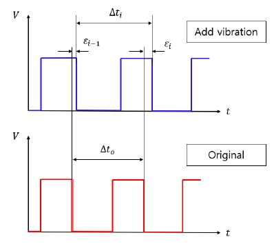
The angular velocity of the shaft corresponding to the ith pulse in Fig. 4 can be calculated as Eq. (2), following equation.
| (2) |
Accordingly, the angular velocity variation of the shaft can be obtained by calculating angular velocity corresponding to each pulse in Fig. 4 using Eq. (2).
3.2 Rotational Vibration Measurement Using Absolute Encoder
In this section, the principle of the measurement of rotational vibration of the shaft using an ordinary absolute encoder will be explained. In the first step of the process, the analogue signal of is sampled with a specific sampling rate to obtain a series of digital signal as shown in Fig. 5.
In the case of the constant angular velocity, the slopes of individual digital data will be constant since the slopes are proportional to the angular velocity at the time slot. On the other hand, the slopes for the individual points will have variation with time when the shaft have rotational or torsional vibration. So, the rotational vibration of the shaft can be calculated based on the slopes of individual data points in Fig. 6.
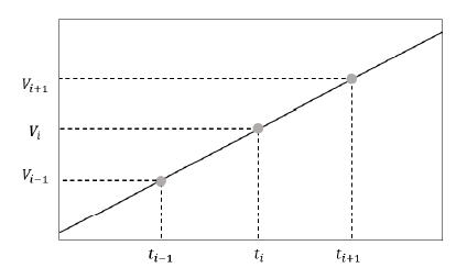
Figure 6 explains arbitrary 3 points on the sampled voltage data. Rotation angle (θi) and angular displacement (∆θi) for the ith time slot can be obtained as Eq. (3a) and Eq. (3b) following equations.
| (3a) |
| (3b) |
Angular velocity of the ith time slot can be obtained by dividing ∆θi with time interval (∆ti=ti+1-ti). In addition, since the voltage output of the encoder is sampled at a constant time internal, ∆ti is constant for all the data points as ∆t. Consequently, angular velocities for each point can be calculated as Eq. (4).
| (4) |
By repeating this process for a specific time interval, the rotational velocity variations or rotational vibration of the shaft for the time interval can be obtained.
4. Validations of Rotational Vibration Measurement Process
In this section, two methods for the measurement of rotational vibration using incremental and absolute encoders will be compared numerically and experimentally. In the numerical comparison, the results from the numerical calculations simulating the measurements using incremental and absolute encoders will be compared with each other. Also, in the experimental comparison, rotational vibrations of the shaft measured with the two processes will be compared with each other.
4.1 Simulation
In this section, rotational vibration measurement results are simulated using computer simulations. The rotational speed of the shaft in these simulations is assumed to be as Eq. (5) with the first and second order rotational vibration along with nominal speed of rotation.
| (5) |
In this equation Ω is the nominal speed of shaft and Ω1 and Ω2 are the magnitudes of the first and second order rotational vibration of the shaft. The rotation angle of the shaft can be obtained as Eq. (6) by integrating the speed of shaft with respect to time.
| (6) |
In this simulation, the imaginary shaft is assumed to be rotating with the angular velocity given in Eq. (5) along with the parameters given in Table 1.
As explained above, the incremental encoder generates a square pulse as θ increases in pre-determined amount 2π/PPR and the absolute encoder generates a triangular pulse as θ increases by 2π rad. Also, the output signals from the encoders are sampled by a data recorder for the analyses in the computers. The simulation parameters for the output signals and data recorders are given in Table 2.
In addition, 0.5 % random error is added to the output signals from the encoders to consider the imperfectness of the encoders.
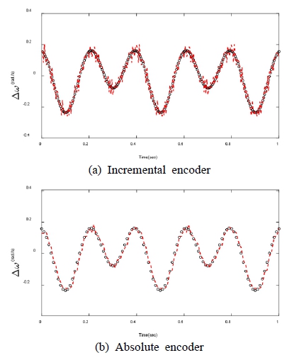
The simulation results for the two encoders under the conditions described in Table 1 and Table 2 are compared with each other and with rotational vibration which is introduced intentionally. The time data for the variations of angular velocities are compared in Fig. 7(a) and Fig. 7(b).
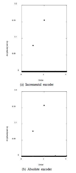
As one can see in the figures, ∆ωi from the incremental and absolute encoder and those for the intentionally introduced are quite well match each other. But, the effect of the random error is more dominant in the result of the absolute encoder. In addition, Fourier transform results of above data are explained in Fig. 8(a) and Fig. 8(b).
As shown in the figure, the first (2.5 Hz) and second order (5.0 Hz) rotational vibrations which are intentionally introduced in the simulations are clearly identified in the simulation results for the two processes. Also, the magnitudes of the vibration of individual components obtained from two processes are listed in Table 3 along with theoretical values.
As shown in the table, the magnitudes of the first and second order vibrations are almost same as those of intentional rotational vibrations. Consequently, based on the results in Fig. 7 and Table 3, it can be concluded that the proposed processes have enough accuracies in the measurement of the rotational vibration of the shaft.
4.2 Experimental Verification
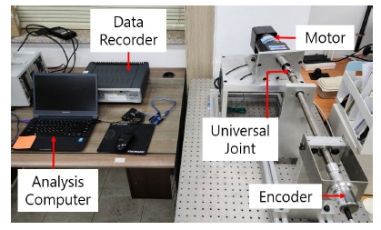
The test setup for this study is explained in Fig. 9. As shown in the figure, the setup is composed of a shaft and a motor connected to each other with a universal joint. At the end of the shaft, an encoder is attached to measure rotational vibration of the shaft. The signals from the encoders are processed with a data recorder and a computer.
In the test with the incremental encoder, an incremental encoder W-60 from Autonics is used along with Virtex-ⅡXC2V3000 FPGA data recorder. The output signal from the encoder sampled with the frequency of 1 mHz by the data recorder is analyzed by a computer to obtain the angular velocity of the shaft at the end of each pulse. For the experiment with the absolute encoder, an absolute encoder MCD-AC005-0412-M100-CAW from POSITAL Co. is used. This encoder generates a triangular pulse for every 16 rotations of the shaft.
If a pair of shafts are connected by a universal joint, the speeds of the input (ωA) and output (ωB) shafts have following relation(15) of Eq. (7).
| (7) |
In this equation, θ is the intersection angle of two shafts a is the rotation angle of the input shaft. As one can imagine from the equation, ωB has two sinusoidal variation per revolution with max. speed of ωA/cosθ and min. speed of ωAcosθ(15). Obviously, there will be no dominant rotational vibration component when θ=0⁰ but there will be the second order rotational vibration with magnitude of 6 % of nominal speed of the shaft when θ=20⁰.
In this section, the rotational vibration of the shaft in the test setup measured with incremental and absolute encoders as explained in Section 2 and 3. The two results are compared with each other for the two cases θ=0⁰ and θ=20⁰. Also, the motor speed is set to 150r/min.
The time signals from two methods are compared with each other in Fig. 10. As shown in the figure, the signals from two methods matches quite well each other in both cases.
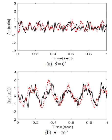
Time data for the variation in the rotational speed of the shaft (key: ━━ Absolute encoder, - - - Incremental encoder)
In addition, in the case of θ=0⁰ the time signals have no dominant periodic variation while those for the case θ=20⁰ have apparent periodic variation with period of 0.2 s. In both cases, small irregular variations due to asymmetries, offset and unbalanced mass are included in the signals. Also, in the case of θ=20⁰ the amplitude of variation of period 0.2 s. is close to 1.0rad/s. which is 6 % of the nominal speed of the shaft. Also, the results from two processes with two types of encoders match quite well each other in two cases verifying that the proposed processes have sufficient accuracies in measuring rotational vibration.
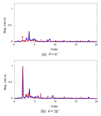
As the next step, the frequency contents in rotational vibration of the shaft are identified by the frequency analyses in the form of order components of nominal speed of the shaft.
The results of frequency analyses of the outputs of processes with incremental and absolute encoders are compared in Fig. 11. In the case of θ=0⁰ no dominant order component can be identified in the results of both processes, as shown in the Fig. 11(a). But, in the case of θ=20⁰ the second order component is identified as a dominant component in the results of both processes, as shown in the Fig. 11(b). Also, the results from two processes are similar to each other, especially in the dominant order component. Also, both results include small components of vibration from uncertainties of the setup. Also, in the case of θ=20⁰ the amplitude of the second order vibration is close to 1.0rad/s which is 6 % of the nominal speed of the shaft.
5. Conclusions
In this study, the measurement of rotational vibration with two types of encoders, i.e. incremental and absolute encoders are comparatively investigated. The measurement processes for two methods are introduced in the first stage. Then the proposed processes are examined using computer simulation verifying the validity of the proposed processes.
In the next step, the processes are experimentally validated using simple test setup. In the experiments, two types of encoders measured the rotational vibration of the shaft having the rotational vibration generated by a universal joint and a driving motor. The intersection angle of the universal joint θ is set to be 0⁰ and 20⁰ to control the rotational vibration in the shaft. The measurement results from two types of encoders are compared in time and frequency domains. The results from two types of encoders match quite well each other and theoretical calculations validating accuracies of the proposed processes. When θ=0⁰, no dominant component is observed but when θ=20⁰ the second order vibration is identified as dominant component with the amplitude which is almost identical to the theoretical prediction. So, it can be concluded that the two procedures for the rotational vibration measurement using ordinary incremental and absolute encoders have sufficient accuracies.
The problems in the real applications of the proposed processes and corresponding countermeasures will be investigated in the subsequent studies.
References
-
Li, M., Khonsari, M. and Yang, R., 2018, Dynamics Analysis of Torsional Vibration Induced by Clutch and Gear set in Automatic Transmission, International Journal of Automotive Technology, Vol. 19, No. 3, pp. 473~488.
[https://doi.org/10.1007/s12239-018-0046-8]

-
Liu, X., Wu, Z., Lu, J. and Xu, J., 2019, Investigation of the Effect of Rotation Speed on the Torsional Vibration of Transmission System, Journal of Advanced Mechanical Design, Systems, and Manufacturing, Vol. 13, No. 4, 19-00324.
[https://doi.org/10.1299/jamdsm.2019jamdsm0079]

-
Wu, G., Shi, W. and Chen, Z., 2013, The Effect of Multi-universal Coupling Phase on Torsional Vibration of Drive Shaft and Vibration of Vehicle, SAE Technical Paper, 2013-01-1490.
[https://doi.org/10.4271/2013-01-1490]

-
Yacamini, R., Smith, K. S. and Ran, L., 1998, Monitoring Torsional Vibrations of Electro-mechanical Systems Using Stator Currents, Journal of Vibration and Acoustics, Vol. 120, No. 1, pp. 72~79.
[https://doi.org/10.1115/1.2893829]

-
Song, Z., Liu, Y., Guo, P. and Feng, J., 2018, Torsional Vibration Analysis of Hydro-generator Set Considered Electromagnetic and Hydraulic Vibration Resources Coupling, International Journal of Precision Engineering and Manufacturing, Vol. 19, No. 7, pp. 939~945.
[https://doi.org/10.1007/s12541-018-0111-2]

-
Diangui, H., 2000, Experiment on the Characteristics of Torsional Vibration of Rotor-to-stator Rub in Turbomachinery, Tribology International, Vol. 33, No. 2, pp. 75~79.
[https://doi.org/10.1016/S0301-679X(00)00029-3]

- Klubnik, R., 2008, Measuring Displacement Using Accelerometers, Maintenance Technology, Vol. 21, No. 3, p. 30.
-
Miles, T. J., Lucas, M., Halliwell, N. A. and Rothberg, S. J., 1999, Torsional and Bending Vibration Measurement on Rotors Using Laser Technology, Journal of Sound and Vibration, Vol. 226, No. 3, pp. 441~467.
[https://doi.org/10.1006/jsvi.1999.2253]

-
Javed, A., Lee, H., Kim, B. and Han, Y., 2022, Vibration Measurement of a Rotating Cylindrical Structure Using Subpixel-based Edge Detection and Edge Tracking, Mechanical Systems and Signal Processing, 166, 108437.
[https://doi.org/10.1016/j.ymssp.2021.108437]

-
Resor, B. R., Trethewey, M. W. and Maynard, K. P., 2005, Compensation for Encoder Geometry and Shaft Speed Variation in Time Interval Torsional Vibration Measurement, Journal of Sound and Vibration, Vol. 286, No. 4-5, pp. 897~920.
[https://doi.org/10.1016/j.jsv.2004.10.044]

-
Negrea, A. C., Imecs, M., Incze, I. I., Pop, A. and Szabo, C., 2012, Error Compensation Methods in Speed Identification Using Incremental Encoder, Proceedings of 2012 International Conference and Exposition on Electrical and Power Engineering, pp. 441~445.
[https://doi.org/10.1109/ICEPE.2012.6463857]

-
Remond, D., 1998, Practical Performances of High-Speed Measurement of Gear Transmission Error or Torsional Vibrations with Optical Encoders, Measurement Science and Technology, Vol. 9, No. 3, 347.
[https://doi.org/10.1088/0957-0233/9/3/006]

-
Nam, S., Baik, K. and Cheung, W.-S., 2014, Calibration System for Angular Vibration Using Precision Rotary Encoder, The Journal of the Acoustical Society of Korea, Vol. 33, No. 1, pp. 31~39.
[https://doi.org/10.7776/ASK.2014.33.1.031]

-
Lee, H., 2022, Study on Rotational Vibration Measurement Using an Ordinary Absolute, Transactions of the Korean Society for Noise and Vibration Engineering, Vol. 32, No. 5, pp. 471~478.
[https://doi.org/10.5050/KSNVE.2022.32.5.471]

-
SYanying, G., Zhonghui, S. and Zhonghong, S., 2008, The Kinematics Analysis on Single Cross Universal Joint, Proceedings of 2008 IEEE Vehicle Power and Propulsion Conference, pp. 1~3.
[https://doi.org/10.1109/VPPC.2008.4677771]


Gyubin Kwak Bachelor's degree in Automotive Engineering from the Kyungpook National University in 2019. Also he is studying for his Ph.D. degree in the Kyungpook National University.

Hyung-Ju Cho Ph.D. in computer science and Professor in the Department of Software, Kyungpook National University. His current research interests include moving object databases, query processing in mobile peer-to-peer networks, and real-time maintenance of the high-definition digital map for autonomous vehicles.

Hyeong-Ill Lee Ph.D. in mechanical engineering and Professor in the School of Automotive Engineering, Kyungpook National University. Professor Lee is teaching Dynamics, Automatic Control and Mechanical Vibration, etc. He has academic interests in automotive NVH, Brake squeal, Sound radiation from vibrating structures, etc.
