전기차 일체형 모터 감속기 축 거동과 기어 진동 상관관계에 대한 연구
© The Korean Society for Noise and Vibration Engineering
Abstract
Dynamic and static shaft eccentricity in integrated electric motor-reducers can lead to variations in the motor air gap and elevate both the motor and gear noise levels. This study investigates the effects of static and dynamic eccentricity, along with the presence of wave washers, on the gear noise of an integrated electric motor-reducer system. The results indicate that shaft eccentricity substantially increases both the orbit radius and width magnitude, with enhancements of up to 1.33 times and 4.57 times, respectively, under static and dynamic eccentricity conditions. Although the axial motion remains relatively small (under 10 μm), its magnitude is intensified by the absence of wave washers and the presence of eccentricity. A novel correlation between shaft motion and gear vibration was identified, illustrating that shaft movement induced by eccentricity has a direct impact on gear meshing dynamics. The absence of wave washers, coupled with static eccentricity, was associated with a maximum increase of 25 dB in gear vibration. These findings underscore the critical importance of closely regulating shaft eccentricity and related parameters to optimize motor-reducer performance and minimize gear noise in electric vehicles.
Keywords:
Rotor Shaft Movement, Eccentricity, Gear Noise키워드:
로터 축 거동, 편심, 기어소음1. 서 론
모터와 감속기로 구성된 전기 자동차 구동계에서 발생하는 소음은 모터 소음, 스위칭 소음, 회전축에 의한 부밍 소음, 럼블성 소음과 기어 소음 등으로 크게 구분할 수 있다. 특히 모터 회전축의 이상 거동은 회전체 성분에 의한 소음의 주요 원인이다. 일반적으로 축 이상 거동을 유발하는 요인은 동적 편심과 정적 편심, 복합 편심 등이 있다. 이러한 편심에 의해 모터에서는 에어갭(airgap) 등이 변화되면서 모터 성능과 소음 등에 영향을 미치고 축에 조립된 기어 소음 등에도 영향을 미친다. 영구자석형(PMSM)모터의 로터 축과 기어 사이의 조립 오차, 로터의 질량 편차, 베어링 결함 등이 있으면 로터의 편심을 유발하여 비대칭적인 에어갭이 형성되면서 균형이 맞지 않는 자기력인 UMP(unbalanced magnetic pull)이 발생하기도 한다(1~4). 감속기 측면에서는 기어를 축에 압입하여 조립하는 과정에서 기어 치의 형상 변화가 발생하기 때문에 이러한 변화를 예측하기 위한 해석 기법 수립이 필요하며 조립시 기어 치형 변형 등을 고려한 기어 치형 수정을 미리 해야 한다는 연구 등이 있다(5). 또한 기어가 장착된 축의 회전 속도와 전달 토크가 커짐에 따라 베어링 강성이 커져서 축의 굽힘 고유진동수를 증가시킨다는 연구와 카메라를 이용한 영상 분석으로 개방된 축의 진원도를 측정하는 연구도 수행된 바 있다(6~7).
모터 로터축 연구에서는 상용 프로그램을 이용하여 회전축의 정적 진동 특성을 고려하여 사다리꼴의 중공축 단면 설계안을 제시하기도 하였다(8). 그러나, 양산품 모터와 감속기의 고속운전 조건에서 축 거동은 모터 운전시에 발생하는 전기적 노이즈와 폐쇄되고 협소한 공간적 제약, 기어의 치접촉에 의한 동력전달시 발생하는 추력 등으로 동적 운전시 축 거동 측정 자체가 어렵기 때문에 연구가 미흡한 실정이다.
이 연구에서는 전기적 노이즈의 영향을 받지 않는 갭센서를 개발하였다. 그리고 현재 양산되고 있는 일체형 모터 감속기 제품에 대하여 정적(static) 편심과 동적(dynamic) 편심이 발생되는 조건을 구현하고 모터 구성 부품 중 하나인 웨이브와셔 유/무 등에 따른 영향성 평가를 운전하는 동적 상태에서 실시하여 축의 반경 및 축 방향 거동과 이에 따른 기어 진동 수준 변화와의 상관성을 확인하였다. 이 연구 결과를 토대로 기어 진동의 영향 인자 등을 발굴하여 일체형 모터 감속기의 소음 진동 품질 안정화와 후속 모델의 설계에 참고하고자 한다.
2. 본 론
2.1 준비 과정
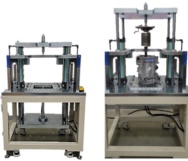
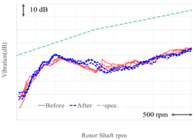
이 연구를 진행하기 위한 동적 편심과 정적 편심을 가진 모터 감속기를 구성하기 위하여 Fig. 1과 같이 일체형 모터 감속기 분해 조립 장비를 개발하였다. 일반적으로 모터와 감속기 구성의 회전축 편심은 모터와 감속기 하우징의 위치 공차와 베어링 경의 공차 등이 고려된다. 이때 편심이 발생할 수 있는 설계 최대값은 ‘A’ μm 정도이다. 그러나 기어를 모터 축에 압입하여 조립할 때, 특정 환경에서 최대 설계치보다 2배 이상 큰 런아웃(run-out)이 발생하기도 한다. Fig. 2는 개발된 모터 감속기 분해 조립 장비를 이용하여 모터 감속기를 여러 번 분해 조립하고 대상에서 평가하여 그 결과의 반복성을 점검한 결과이다. 기어의 진동 산포가 약 2 dB ~ 3 dB 이내로 양호하여 평가를 위한 장비가 신뢰할 수 있음을 확인하였다.
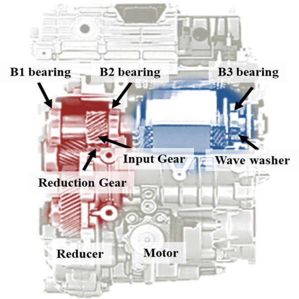
Fig. 3은 일체형 모터 감속기의 절개품을 도시한 것이다. 이 연구를 위하여 모터 구동축의 편심을 제어하고 이의 거동을 확인하기 위하여 B1, B2 베어링과 웨이브와셔(wave washer) 유/무를 축 거동의 제어 인자로 선정하였다.
2.2 축의 편심 구성
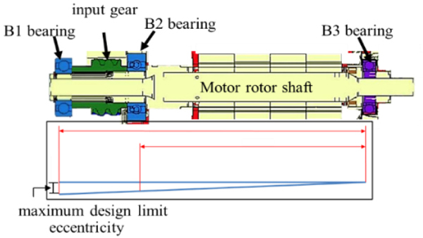
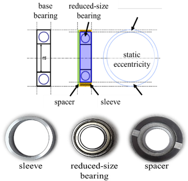
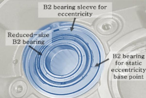
Fig. 4와 같이 축을 지지하는 B1, B2 베어링부를 조정하여 설계 및 제조상 발생할 수 있는 최대 축 편심을 구현하였다. 이를 위하여 Fig. 5와 같이 B1과 B2 베어링을 기존 베어링과 내경 ‘a’는 동일하나 외경과 폭이 작은 베어링으로 대체하였다. 외경과 폭이 작아진 베어링을 케이스에 조립하여 정적 편심과 동적 편심을 만들 수 있도록 하기 위하여 기존 베어링의 외경과 폭을 보상할 수 있는 스페이서(spacer)와 슬리브(sleeve)를 제작하였다. 정적 편심은 베어링의 위치에 따라 영향을 받도록 Fig. 5와 같이 베어링의 외경과 접하는 슬리브의 내경을 편심되도록 제작하였으며 동적 편심은 슬리브 내경과 베어링 외륜사이에 일정한 공차를 부여하여 기어에 의해 축이 회전하면 자연스럽게 공차에 의한 편심이 발생하도록 구성하였다. Fig. 6은 모터 하우징에 리덕션 기어쪽으로 정적 편심이 발생하도록 구성한 B2 베어링을 조립한 예를 보인 것이다(9).
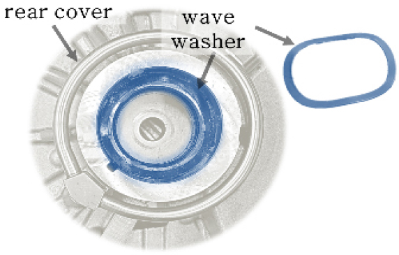
Fig. 7은 모터의 B3 베어링이 있는 곳의 리어 커버(rear cover) 내부의 웨이브 와셔(wave washer)를 보인 것으로 모터 조립 조건 등에 따라 일정한 수준의 추력을 유지하는 역할을 한다.
2.3 갭 센서
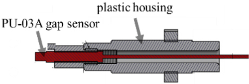
일체형 모터 감속기에서 회전자와 고정자가 위치하는 공간 특성과 동력을 전달할 때 발생하는 고전압 전기 노이즈 등의 영향으로 갭 센서를 이용하여 축 거동 현상을 계측하고 분석하는 것은 어려운 일이다. 전기 노이즈에 의한 데이터 오염의 문제를 해결하기 위하여 Fig. 8과 같이 전기 노이즈 절연을 위한 플라스틱 하우징과 5 mV/μm의 민감도를 가진 갭 센서 모듈(gap sensor module)을 개발하였다.
2.4 대상 평가 준비
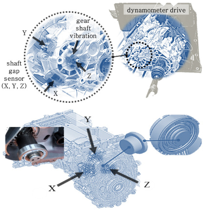
Fig. 9는 대상셀에서 일체형 모터 감속기의 인풋 축거동과 기어 진동을 측정하기 위하여 설치한 것을 보인 것이다(10). B1 베어링부 근처에 X, Y, Z 방향의 갭센서를 설치하고 10 mV/g의 민감도를 가진 ICP (integrated circuit piezoelectric) 타입의 3축 가속도 센서를 설치하고 500 r/min에서 5000 r/min까지 가속과 감속, 그리고 500 r/min단위로 정속 조건으로 운전하면서 데이터를 확보하였다.
2.5 반경 방향 거동
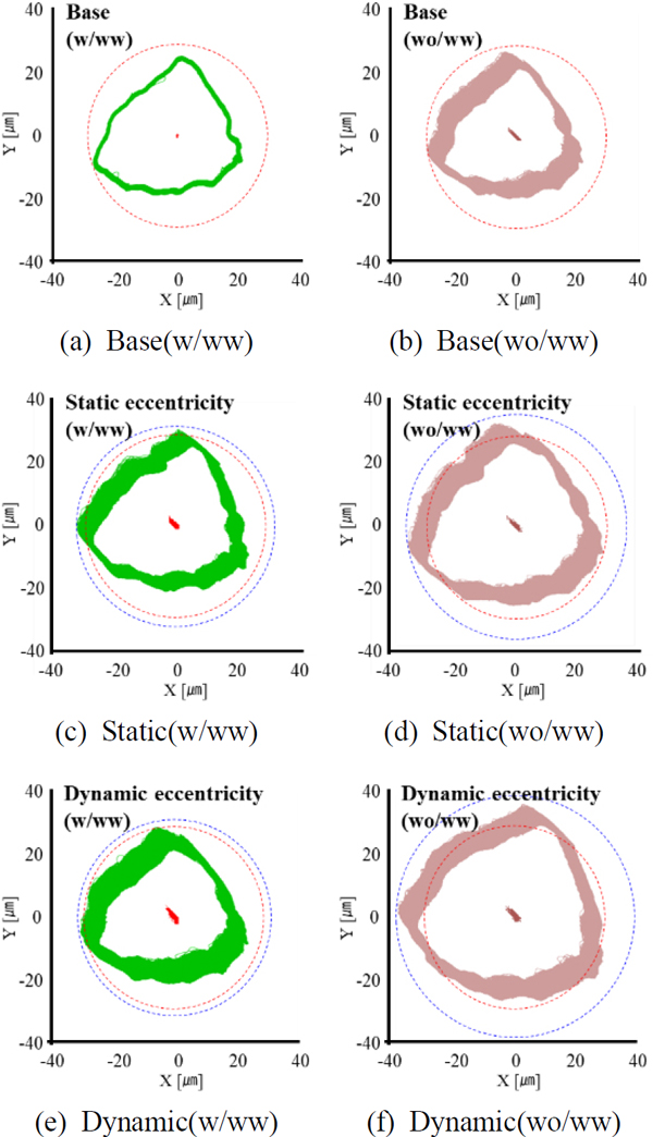
Fig. 10은 가속조건에서 베이스품, 정적 편심, 그리고 동적 편심 조건과 웨이브 와셔 유/무 등에 따른 축의 회전 궤적인 오르빗(orbit)을 계측한 것을 도시한 것이다. 오르빗의 중심에서부터 최외각까지의 거리를 반경으로 하는 원을 붉은 점선(베이스품)과 파란 점선(편심 조건에 따른 크기)로 각각 표현하였다.
Comparison of rotor shaft orbit results(base, static, and dynamic eccentricity conditions with and without wave washer under acceleration condition)
웨이브 와셔가 없으면 웨이브 와셔가 있을 때 보다 반경 방향 오르빗의 크기가 커지는 것을 확인할 수 있다. 또한 정적 편심과 동적 편심이 가해지면 오르빗의 크기가 점점 커지는 것을 확인할 수 있다.
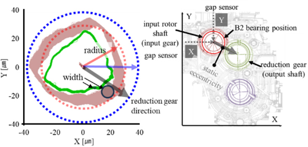
Fig. 11은 웨이브 와셔를 가진 베이스품과 웨이브와셔가 없는 동적 편심 조건에서의 축의 오르빗을 계측한 것을 비교한 것이다. 오르빗의 반경(radius)이 커졌으며, 거동의 폭(width)이 커진 것을 확인할 수 있다. 오르빗 폭의 변화는 인풋 기어가 리덕션기어와 물림이 이루어지는 방향에서 크게 발생한다.
Comparison of rotor shaft orbit radius and width under base with wave washer, and dynamic eccentricity without wave washer conditions
Table 1은 가속과 감속조건에서 웨이브 와셔 유/무 등에 따른 베이스품, 정적 편심, 그리고 동적 편심 조건에서 축거동의 크기 변화를 비교 정리한 것이다. 베이스품의 크기를 ‘1’로 정의하면 웨이브 와셔가 없고 동적 편심이 있으면 축 회전 오르빗 크기가 최대 1.33배 정도 증가한다. 뿐만 아니라, 특정 방향의 오르빗 폭은 최대 4.57배까지 증대된다. 또한 오르빗의 모양이 삼각형이거나 ‘D’ 형상을 가진 것을 확인할 수 있다(10). 일반적으로 축의 오르빗 형상이 원형을 유지하지 않는 것은 축의 흔들림과 정렬 불량, 미끄러짐 등이 있기 때문이다. 기어가 동력을 전달할 때, 기어 치접촉에서 ‘미끄러짐 - 구름 - 미끄러짐’ 운동을 한다. 따라서, 동력을 전달하는 기어가 있는 일체형 모터 감속기의 축 거동은 원형이 아닌 다른 형상의 오르빗이 나타나는 것으로 판단된다.
2.6 축 방향 거동
Fig. 12는 축방향 거동을 측정한 것으로 거동의 편차 크기는 ‘정상 < 동적 편심 < 정적 편심’, ‘웨이브 와셔 장착 < 웨이브 와셔 제거’의 경향을 나타낸다. 무부하 조건에서 측정을 했으나, 기어의 헬릭스각에 의한 추력이 발생하여 축방향 거동이 약 10 μm 발생한다. 실제 하중이 추가되면 거동량은 더 커질 것으로 판단된다.
2.7 기어 진동
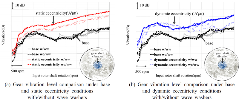
Fig. 13은 대상 무부하 조건에서 모터 감속기를 0.5 k rpm에서 5 k rpm까지 축 편심 조건별로 운전하여 기어 진동 수준을 측정한 결과를 도시한 것이다. 모터 감속기 축의 정적 편심과 동적 편심 등에 의하여 기어 진동이 악화되는 것을 확인할 수 있다.
Comparison of gear vibration results under base, static, and dynamic eccentricity conditions, with and without wave washers, during acceleration from 0.5 k to 5 k rpm
Fig. 13(a)에서 정적 편심이 있는 경우 기어 진동은 최대 20 dB, 정적 편심이 있으면서 웨이브 와셔가 없는 조건에서는 약 25 dB까지 악화된다. Fig. 13(b)에서 동적 편심이 있는 경우에는 약 15 dB 정도 악화된다. 이러한 현상은 기어가 장착된 축의 중심이 틀어지면서 기어의 물림이 이루어지는 치접촉이 영향을 받게 되고 이로 인하여 기어 진동이 커진 것으로 판단된다.
3. 결 론
일체형 모터 감속기의 동적 운전 상태에서 회전축 거동을 측정하는 방법을 개발하고 축의 정렬 조건별 거동과 기어 진동을 측정, 분석하여 다음과 같은 결론을 얻었다.
(1) 일체형 모터 감속기는 베어링과 케이스 제조, 그리고 조립 조건 등에 의하여 축에 정적 편심과 동적 편심 등이 발생할 수 있다.
(2) 설계, 제조 한계 등에 의해 최대 ‘A’ μm 수준의 동적 또는 정적 편심이 발생하고 B3 베어링 위치의 웨이브 와셔 유/무 등에 따라 무부하 조건에서도 축의 회전 방향 축거동의 크기는 최대 1.33배, 반경 방향 거동폭은 최대 4.57배까지 증대되었다.
(3) 축 방향 거동은 무부하 조건에서 기어의 헬릭스각에 의해 약 10 μm 미만의 움직임을 가진다. 그러나, 웨이브 와셔가 없는 경우에는 그 크기가 2 μm ~ 3μm 더 커지며, 축의 편심이 있는 경우에 그 크기는 더 커진다.
(4) 축의 편심에 의한 거동 상태에 따라 기어 진동은 정적 편심이 있는 경우 최대 20 dB, 설계 한계치인 ‘A’μm 수준의 정적 편심이 있으면서 웨이브 와셔가 없는 조건에서는 25 dB까지 악화된다. 동적 편심이 있는 경우 약 15 dB 정도 악화된다. 이는 축 편심에 의해 기어의 치접촉이 직접적으로 영향을 받아 기어 진동이 커진 것으로 판단된다. 따라서 모터 감속기 가공 부품의 품질과 조립 등에서 발생하는 축 편심 품질로 기어의 진동 산포가 25 dB까지 커질 수 있다는 의미이기도 하다.
(5) 이 연구의 결과는 고속 모터 감속기를 개발할 때, 축을 지지하는 요소들의 설계 공차와 제조 편차 관리에 있어서 더욱 특별한 관리가 필요하다는 것을 보여준다.
(6) 향후, 동일한 모터 감속기에서 기어 제원에 따른 축 거동의 변화에 대한 연구를 통하여 저소음 기어 제원과 축 거동 특성과의 상관관계를 규명해 보고자 한다.
References
-
Dupont, J. B., Aydoun, R. and Bouvet, P., 2014, Simulation of the Noise Radiated by an Automotive Electric Motor: Influence of the Motor Defects, SAE International Journal of Alternative Powertrains, Vol. 3, No. 2, pp. 310~320.
[https://doi.org/10.4271/2014-01-2070]

-
He, S., Zhang, P., Gandham, M., Omell, B. and Grewe, T. et al., 2020, Three Dimensional Electromagnetic and NVH Analyses of Electric Motor Eccentricity to Enhance NVH Robustness for Hybrid and Electric Vehicles, SAE Technical Paper 2020-01-0412.
[https://doi.org/10.4271/2020-01-0412]

-
Ruf, A., Schröder, M., Putri, A. K., Konrad, R., Franck, D. and Hameyer, K., 2014, Analysis and Determination of Mechanical Bearing Load caused by Unbalanced Magnetic Pull, COMPEL - The International Journal for Computation and Mathematics in Electrical and Electronic Engineering, Vol. 35, No. 2, pp. 728~743.
[https://doi.org/10.1108/COMPEL-03-2015-0111]

-
Zhang, A., Bai, Y., Yang, B. and Li, H., 2018, Analysis of Nonlinear Vibration in Permanent Magnet Synchronous Motors under Unbalanced Magnetic Pull, Applied Sciences, Vol. 8, No. 1, p. 113.
[https://doi.org/10.3390/app8010113]

-
Joshi, Y. V., 2018, Gear Interference-fit Joint Considerations and Design for the Resultant Tooth Distortion, SAE Technical Paper 2018-01-1293.
[https://doi.org/10.4271/2018-01-1293]

- Park, S. K., 1995, Dynamic Charatristics of a Rotor-journal Bearing System Driven by Gearboxes, Journal of KSNVE, Vol. 5, No. 4, pp. 565~576.
-
Son, K.-S., Jeon, H.-S., Park, J.-H. and Park, J. W., 2014, A Technique for Vibration Measurement and Roundness Assessment of Rotating-axis using Camera Image, Transactions of the Korean Society for Noise and Vibration Engineering, Vol. 24, No. 2, pp. 131~138.
[https://doi.org/10.5050/KSNVE.2013.24.2.131]

-
Park, S. J. and Lee, J. W., 2024, Cross-section Design of Hollow Shafts to Improve Static and Vibration Characteristics of Rotating Shafts, Transactions of the Korean Society for Noise and Vibration Engineering, Vol. 34, No. 4, pp. 432~439.
[https://doi.org/10.5050/KSNVE.2024.34.4.432]

- Lee, H. K. and Kim, M. S., 2024, An Experimental Investigation of the Correlation between Shaft Static and Dynamic Eccentricity, Counter Electromotive Force, Magnetic Flux Density and Gear Noise in Motor Reducer Systems, Proceedings of the 37th International Electric Vehicle Symposium & Exhibition, Seoul, Korea.
- Lee, H. K., Kim, M. S., Lee, J. H. and Lee, M. U., 2024, A Study on the Correlation between Integrated E-motor Reducer Shaft Movement and Gear Noise, Proceedings of the KSNVE Annual Spring Conference, p. 353.

Hyun Ku Lee is a NVH global R&D master engineer in the Hyundai - Kia Motors Research and Development Division. He received his B.S. and M.S. degrees of Mechanical Engineering from The Konkuk University in 1995 and in 1997 respectively. He won a Jang Young-sil Award in 2010 and won the 1st Yang Bo Suk Technical Award in 2016 from the KSNVE. He has developed several 6th and 8th-speed automatic transmissions, a CVT, and equipment for measuring transmission errors in external gear and planetary gear sets. Additionally, he developed a pRMC and PTA program for planetary gear design and has authored several papers on automatic transmission and reducer gear noise. Currently, his research focuses on driveline noise, particularly related to planetary gear NVH and efficiency, EOL, transmission error, total backlash, as well as noise and vibration in electric vehicle reducers and in-wheel motors.
